Tap Changer: Complete Industry Guide – Definition, Types, Specifications, Selection & Applications
What is a Tap Changer?
A tap changer is a critical electromechanical switching device fitted inside power and distribution transformers, designed to adjust the transformer winding turns ratio for active voltage regulation. Transformer windings are manufactured with multiple tapping points along the coil length. By switching the electrical connection between these taps, the tap changer modifies the number of active winding turns, raising or lowering the secondary output voltage to counteract grid voltage fluctuations, load variations, transmission line losses, and power generation volatility.
Stable voltage levels are essential to protect motors, electronic equipment, and industrial machinery from overvoltage or undervoltage damage. Without properly configured tap changers, power quality deteriorates, equipment efficiency drops, and premature component failure becomes common. Tap changers are widely recognized as one of the most vital transformer accessories for transmission substations, distribution networks, renewable energy power plants, and heavy industrial power systems.
Basic Structure & Operating Principle
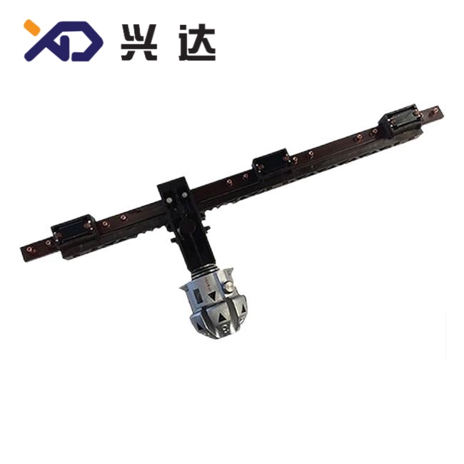
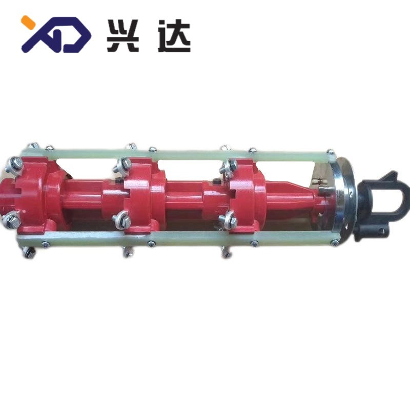
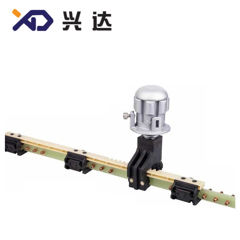
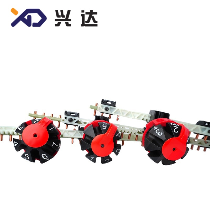
Core Components of Tap Changers
- Selector Switch: Selects the target winding tap position and carries continuous load current.
- Diverter Switch: Exclusive to On-Load Tap Changers (OLTC); performs make-before-break switching to transfer load current and manage electric arcs.
- Transition Impedance: Transition resistor or reactor that limits circulating current during tap shifting.
- Drive Mechanism: Motor gearbox assembly with manual override for mechanical rotation.
- Tap Position Indicator: Local and remote signal module to display current tap location.
- Insulation Housing: Oil compartment or vacuum enclosure isolating switching contacts.
Auxiliary Accessories: Breather, oil level gauge, sampling valve and pressure relief device.
Working Principle
Transformer voltage conversion follows the turns ratio law. When the tap changer selects different winding taps, the effective number of primary or secondary winding turns changes.
- Increasing primary turns reduces secondary voltage
- Reducing primary turns raises secondary voltage
The key engineering difference between tap changer variants lies in whether tap switching can occur while the transformer remains energized. OLTC units adopt a make-before-break sequence. Two contacts briefly bridge adjacent taps, and transition impedance restricts dangerous circulating current before completing the switchover, avoiding power interruption. De-energized tap changers have no transition circuit and can only operate with the transformer fully isolated and de-energized.
Main Classification of Tap Changers
1. Classification by Operating Condition
| Type | Common Aliases | Core Characteristics | Typical Tap Step Range | Primary Applications |
|---|
| De-Energized Tap Changer (DETC) | Off-Circuit Tap Changer, No-Load Tap Changer, OCTC | Tap adjustment only after transformer shutdown; simple mechanical structure, no arc suppression components | ±2×2.5%, ±4×2.5% | Distribution transformers, pole-mounted transformers, static industrial transformers with infrequent voltage adjustment |
2. Classification by Installation Environment
Key Advantages & Limitations of Tap Changer Types
De-Energized Tap Changer (DETC)
- Simple mechanical layout with fewer moving parts and low failure risk
- Competitive procurement cost and minimal routine maintenance
- Compact installation footprint, easy integration into standard distribution transformers
- Long mechanical service life with stable electrical performance
- Tap adjustment requires planned transformer outage
- Unable to perform real-time dynamic voltage regulation for fluctuating loads
- Only suitable for seasonal or long-term static voltage correction
Standard Technical Parameter Overview
| Specification | General Parameter Range |
|---|
| Rated Voltage Class | 10kV, 24kV |
| Rated Current | 30A ~ 250A (customizable for special high-current designs) |
| Standard Tap Regulation Range | ±2×2.5%, ±4×2.5%, ±8×1.25%, ±10×1%, ±16×1.25% |
| Step Voltage | 0.8% ~ 2.5% of transformer rated voltage |
| Mechanical Endurance | DETC: ≥1,000,000 operations; OLTC: ≥500,000 operations |
| Operation Medium | Mineral insulating oil, vacuum, air (dry type) |
| Control Mode | Local manual operation, motorized electric drive, remote automatic control |
| Applicable Standards | IEC 60214-1, IEC 60214-2, IEC 60076, IEEE C57.131, ANSI C57 series |
| Operating Ambient Temperature | -40°C ~ +45°C |
Common Material Selection for Tap Changer Components
Material selection directly determines conductivity, wear resistance and insulation reliability.
| Component | Standard Materials | Performance Purpose |
|---|
| Main Contacts | Silver-alloy copper, copper-tungsten composite | High conductivity, anti-arc erosion, low contact resistance |
| Transition Resistor | Nickel-chromium alloy wire | Stable resistance under short-time overload current |
| Insulation Parts | Electrical pressboard, epoxy resin, ceramic | High dielectric strength, thermal stability inside oil tank |
| Mechanical Housing | Carbon steel, stainless steel | Mechanical protection, corrosion resistance for outdoor transformers |
| Drive Gear Components | Alloy steel | Wear resistance for repeated cyclic operation |
Industrial Applications of Tap Changers
Tap changers serve critical roles across global power infrastructure and heavy industry sectors:
- Power Transmission & Distribution Grids: Substation main transformers, regional distribution transformers, urban power grid voltage stabilization
- Renewable Energy Stations: Wind farm and solar photovoltaic step-up transformers, compensating variable power output voltage drift
- Heavy Industrial Plants: Steel mills, smelters, chemical factories, arc furnace transformers facing violent load fluctuations
- Mining Industry: Underground and surface mining power transformers operating under unstable supply voltage
- Marine & Offshore Power Systems: Platform distribution transformers requiring reliable continuous operation
- Railway Power Supply: Traction transformers for high-speed rail electrification networks
- Commercial Building Power Infrastructure: Large complex dry-type transformers for medium voltage distribution
Tap Changer Selection Checklist
Engineers should evaluate these criteria during specification to avoid operational faults:
- Transformer rated voltage, rated current and winding connection vector group
- Required voltage regulation range and tap step size
- Tap changing frequency: infrequent static adjustment or continuous daily switching
- Operational requirement: energized switching (OLTC) or offline adjustment (DETC)
- Arc extinguishing type: conventional oil-arc OLTC or low-maintenance vacuum OLTC
- Installation type: oil immersed or dry-type construction
- Control configuration: manual operation only, motorized local control or automatic remote regulation
- Regional compliance requirements with IEC, IEEE or ANSI standards
Environmental conditions: indoor, outdoor, coastal salt spray, high humidity or high altitude
Frequently Asked Questions
Q: What is the primary difference between OLTC and DETC tap changers?
A: An On-Load Tap Changer (OLTC) can switch tap positions while the transformer remains energized and loaded, enabling continuous voltage control. A De-Energized Tap Changer (DETC) requires the transformer to be disconnected from the power grid before any tap change, suitable only for infrequent voltage adjustment.
Q: Why are vacuum OLTC designs growing in popularity?
A: Vacuum OLTC uses vacuum interrupters to extinguish switching arcs instead of insulating oil. It avoids oil carbonization, extends oil service cycles, reduces maintenance frequency, and eliminates false DGA fault alarms caused by arcing byproducts.
Q: Where are tap changers normally installed on transformers?
A: Most tap changers are mounted on the high-voltage winding side, where operating current is lower. For special auto-transformer and low-voltage regulating designs, tap arrangements can be configured on the low-voltage winding according to engineering requirements.
Q: How often does an OLTC require maintenance?
A: Maintenance intervals depend on switching frequency. Oil-arc OLTC typically requires oil sampling and inspection every 20,000 to 50,000 operations. Vacuum OLTC can extend service intervals significantly, reducing long-term operational expenditure.