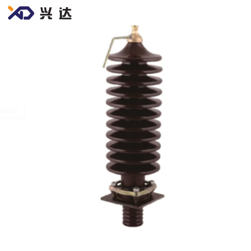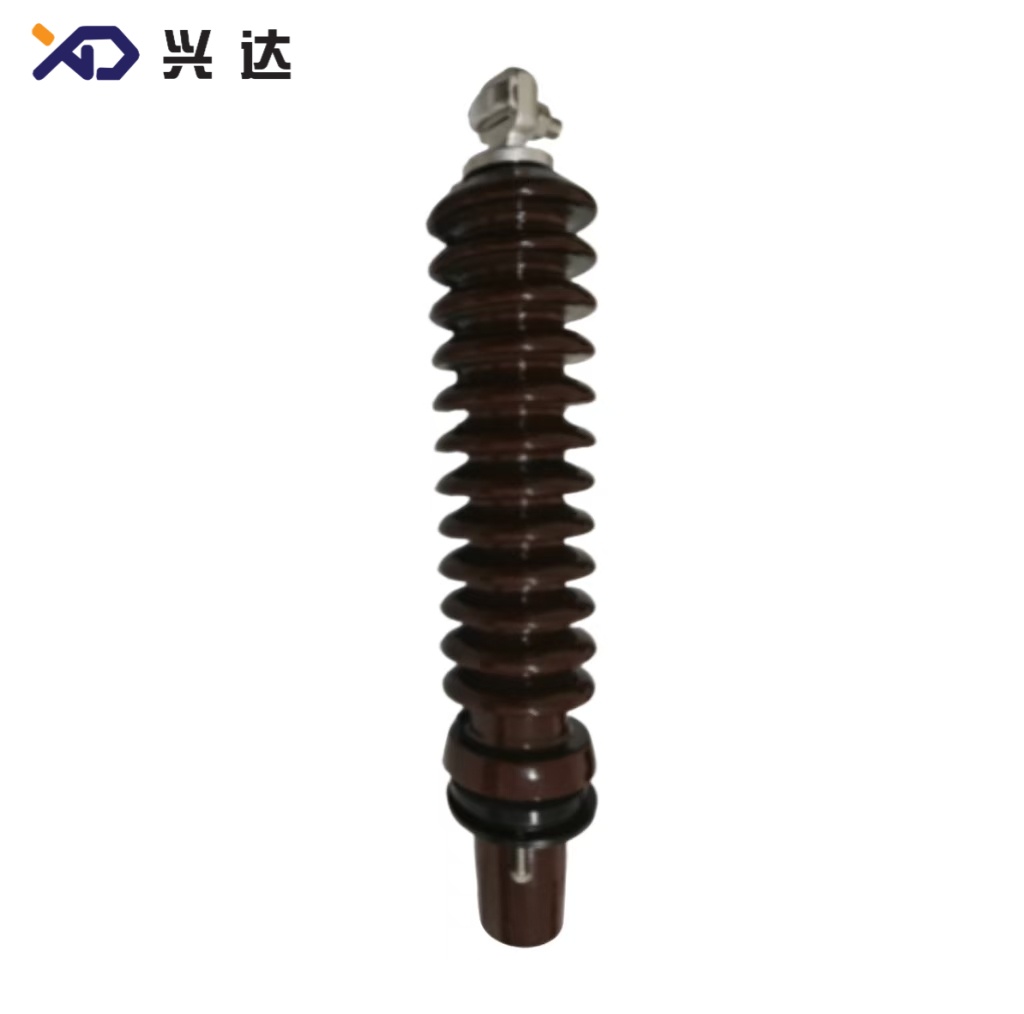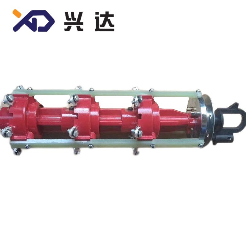
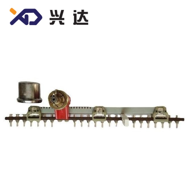
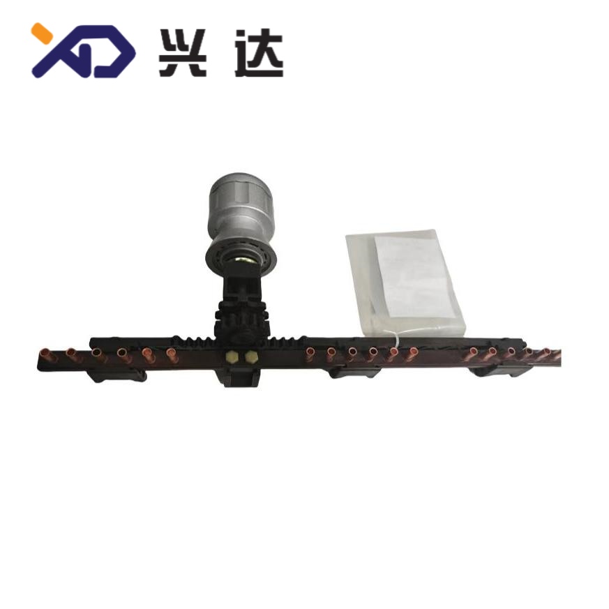
A tap changer is an essential electromechanical switching device mounted on power transformers and distribution transformers. Its core function is adjusting the transformer winding turns ratio by switching between prefabricated tap terminals on high-voltage or low-voltage coils, so as to stabilise output voltage under fluctuating grid supply and variable load conditions.
Grid voltage constantly fluctuates due to peak/off-peak power consumption, long transmission line voltage drop, distributed energy access, seasonal load changes and power grid switching operations. Without voltage adjustment, transformers will deliver unstable voltage, leading to under-voltage or over-voltage problems for end-user equipment. Tap changers eliminate the need for external voltage stabilisers and enable built-in voltage regulation directly inside the transformer unit.
Tap changers are widely applied in medium voltage and high voltage transformers ranging from small distribution transformers to large power station main transformers and substation transformers. The device consists of fixed contacts, moving contact assemblies, operating mechanical structures, and auxiliary drive components. Advanced models integrate vacuum interrupters, transition resistors or reactors for safe current transfer during tap switching.
Transformer output voltage follows the turns ratio law: U1/U2 = N1/N2. Tap points are reserved connection points manufactured along the transformer winding, corresponding to different numbers of coil turns.
When the tap changer shifts its moving contact from one tap position to another, the effective number of winding turns connected to the circuit changes. Adjusting the primary winding turns will raise or lower the secondary output voltage. Most transformers adopt ±2×2.5% or ±4×2.5% tap regulation range, offering multiple discrete voltage levels for selection.
For on-load tap changers (OLTC), a transition circuit is adopted during switching. Transition resistors or reactors temporarily connect two adjacent taps to avoid open-circuit power interruption and prevent dangerous short-circuit circulating current between taps. The whole switching cycle completes within 10–25 milliseconds to guarantee uninterrupted power supply. Off-circuit tap changers only allow switching after the transformer is fully de-energized, so no arc suppression transition circuit is required.
Tap changers can be categorised according to multiple industrial classification standards:
On-Load Tap Changer (OLTC)Also named load tap changer. Supports tap position switching while the transformer remains energized and carrying full load. Automatic voltage controllers can drive OLTC remotely or locally for continuous dynamic voltage stabilisation. Subcategories include resistor-type OLTC, reactor-type OLTC and vacuum interrupter OLTC. Vacuum OLTC is the mainstream modern solution that reduces contact ablation and extends service life.
Off-Circuit Tap Changer (DETC / NLTC)Also called de-energized tap changer or no-load tap changer. Tap adjustment can only be performed after transformer shutdown and power isolation. No-load tap changers feature simpler mechanical structure, lower cost and minimal maintenance demand. They are used for infrequent voltage calibration.
Oil-immersed tap changer: Operates submerged inside transformer mineral oil; the most widely adopted type for medium and high voltage transformers.
Dry-type tap changer: Air-insulated, applied for dry-type distribution transformers in indoor, fire-sensitive environments.
SF6 gas-insulated tap changer: Deployed for special high-voltage and compact substation equipment.
In-tank tap changer: Installed inside the main transformer oil tank.
External compartment tap changer: Equipped with an independent sealed oil compartment, convenient for maintenance without draining the main transformer oil.
| Comparison Item | On-Load Tap Changer (OLTC) | Off-Circuit Tap Changer (DETC / NLTC) |
|---|---|---|
| Operating Requirement | Tap change allowed under energized, loaded state | Transformer must be de-energized before adjustment |
| Voltage Regulation Mode | Dynamic, continuous automatic adjustment | Static manual adjustment, requires planned outage |
| Internal Structure | Equipped with transition resistor / vacuum interrupter, complex mechanical drive | Simple rotary contact structure, no arc suppression parts |
| Typical Regulation Range | ±4×2.5% or wider custom range | ±2×2.5% as standard configuration |
| Mechanical Service Life | 500,000–1,000,000 switching operations | 5,000–10,000 switching operations |
| Unit Cost | Higher | Economical, low investment |
| Maintenance Cycle | Shorter; regular oil testing and contact inspection required | Very long maintenance interval |
| Typical Application | Grid substations, industrial heavy-load transformers, renewable energy step-up transformers | Rural distribution transformers, small commercial transformers, static seasonal voltage correction |
This table covers universal industry standard parameters for conventional oil-immersed tap changers, for engineering selection reference only.
| Parameter Category | Standard Available Range | Notes |
|---|---|---|
| Rated Insulation Voltage | 10kV ~ 400kV | Matched with transformer system voltage class |
| Rated Through Current | 100A ~ 3000A | Single-phase current rating for winding neutral or line end installation |
| Standard Tap Steps | ±2×2.5%, ±4×2.5% | Custom ±1.25%, ±5% steps available on request |
| Number of Tap Positions | 5 positions, 9 positions, 13 positions | 9-position (±4×2.5%) is common for OLTC |
| Max Rated Step Voltage | ≤5000V | Determines insulation design between adjacent taps |
| Operating Temperature Range | -25°C ~ +85°C | Adapted to transformer oil operating temperature |
| Drive Type | Manual hand operation / Motor electric drive | OLTC mostly equipped with 3-phase motor drive unit |
| Contact Material | Copper alloy, silver-plated contacts, copper-tungsten alloy | Silver plating improves conductivity and anti-oxidation performance |
| Compliance Standards | IEC 60214-1, IEC 60214-2, IEEE C57.131 | Global unified testing and performance standards |
| Mounting Arrangement | Neutral point connection / Line end connection | Neutral installation reduces insulation requirement |
Stable End-User VoltageCompensate voltage drop along transmission lines and offset load fluctuation, keeping output voltage within permissible tolerance specified by grid codes. Reduce equipment failure caused by long-term overvoltage or undervoltage.
Optimise Transformer Operation EfficiencyAvoid unnecessary transformer oversizing. Proper voltage regulation lowers reactive power loss and improves overall power system efficiency.
Flexible Adaptation to Grid ChangesAccommodate grid expansion, new load access and photovoltaic / wind power distributed generation voltage variation without replacing transformer main body.
Reduce Additional Power System EquipmentEliminate investment in standalone voltage regulators, shunt reactors and other auxiliary voltage control equipment, simplifying substation layout.
Support Unattended Substation OperationMotor-driven OLTC can cooperate with automatic voltage regulator (AVR) to achieve unmanned remote voltage adjustment, suitable for smart grid construction.
Extend Service Life of Electrical EquipmentSteady supply voltage reduces thermal cycling stress on motors, control panels and consumer electrical devices, lowering long-term replacement and maintenance expenditure.
Tap changers can be installed at the transformer winding neutral point or line end. Neutral-point installation is the mainstream solution for high voltage transformers because it reduces the insulation level required for the tap changer assembly, controlling manufacturing costs. Line-end installation is selected for special transformer designs such as phase-shifting transformers.
Oil-immersed tap changers remain the dominant solution for power transformers worldwide. Mineral oil acts as both insulation medium and cooling medium, and suppresses electric arcs generated during contact switching. Vacuum OLTC limits arcing inside sealed vacuum bulbs, slowing oil contamination and greatly extending oil service intervals compared with traditional oil arc OLTC.
Dry-type tap changers are air-insulated without flammable oil, suitable for indoor shopping malls, data centres, underground substations and other locations with strict fire protection requirements. SF6 gas-insulated tap changers are used in compact GIS-connected transformer projects.
Two sets of standard systems dominate international tap changer engineering:
IEC 60214-1 & IEC 60214-2International standard widely adopted in Europe, Asia, Africa and most global markets. Specifies terminology, design requirements, type test methods, operating conditions and application guidelines for all types of tap changers.
IEEE C57.131Primary North American standard for on-load and off-circuit tap changers, followed in USA, Canada and regions adopting ANSI transformer specifications.
All qualified tap changers must pass a complete test sequence including insulation withstand test, contact resistance test, mechanical endurance test, temperature rise test and short-time current withstand test before factory delivery.
Urban and rural power grid distribution transformers
High voltage transmission substation main transformers
Wind farm and solar power station step-up transformers
Large industrial plant power supply transformers (steel, chemical, mining)
Data centre, hospital and other critical load transformers requiring stable voltage
Railway traction power transformers
Phase-shifting transformers used for power flow control in interconnected grids
Off-circuit tap changers are prioritised for sites where voltage adjustment happens only once or twice per year during seasonal load transition. On-load tap changers are mandatory for locations with frequent voltage swings and zero tolerance for power supply interruption.
Maintenance strategy differs significantly between OLTC and off-circuit tap changers:
Inspect contact resistance every 10–15 years; clean contact surface if oxidation is detected
Check mechanical rotation flexibility during transformer regular overhaul
No regular oil replacement required for integrated designs
Vacuum OLTC: Inspection every 6–10 years or after 100,000 operations
Conventional oil arc OLTC: Oil sampling and testing every 3–5 years; replace tap changer compartment oil periodically
Monitor contact wear and driving motor operating current
Deploy sudden pressure relay and gas monitoring to detect internal faults
Complete tap position calibration after each maintenance operation
A1: Tap changers provide stepwise discrete voltage adjustment. For ultra-fine continuous regulation, tap changers are usually matched with reactive power compensation devices.
A2: Neutral installation lowers insulation requirements and reduces costs, but cannot be applied for delta-connected transformer windings. Selection depends on transformer winding connection group design.
A3: Increased contact resistance leads to local overheating, carbonisation of insulating oil, hot spots and, in severe cases, internal short-circuit faults inside the transformer.
A4: Structural differences make direct modification impossible. Equipment replacement is required if dynamic on-load voltage regulation becomes necessary.
Contact: Tianjin Delda Trading Co., Ltd
WhatsApp: +86 13662056855
Tel:
E-mail: solomon20210701@tjxddq.com
Add: 55-302 Xiaoyuan New Village, Tianjin Economic and Technological Development Zone, China