ANSI Bushing
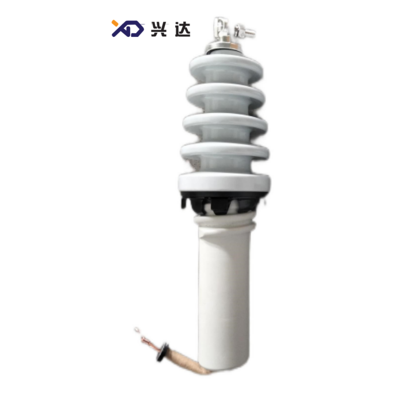
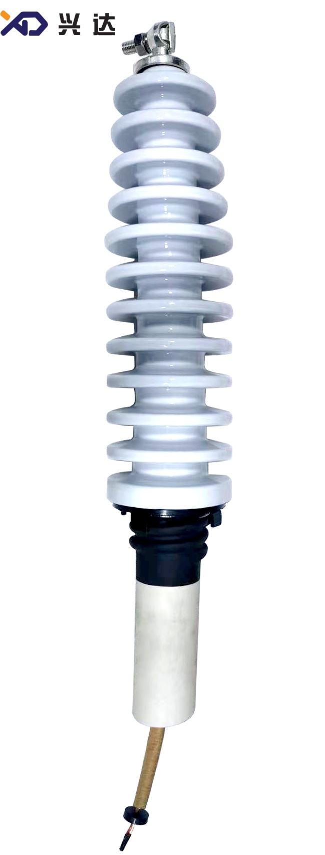
15‑34KV / 125A ANSI Bushing (Through‑rod bushing connector) for Oil‑Immersed Distribution Transformers
15‑34KV / 125A ANSI Bushing (Through‑rod bushing connector)
Overview
Transformer bushings are indispensable insulating and conductive components for oil‑immersed distribution transformers, enabling live internal conductors to pass safely through the grounded metal transformer tank. Within North‑American power infrastructure following ANSI standards, the 15‑34KV / 125A ANSI Bushing (Through‑rod bushing connector) is a widely‑applied medium‑voltage apparatus. Its core design feature is the through‑rod bushing connector, where a solid conductive rod penetrates the full length of the bushing assembly to establish electrical continuity between transformer internal windings and external power circuits.
Medium‑voltage ANSI bushings operate under combined electrical, mechanical and environmental stresses. These include power‑frequency operating voltage, lightning impulse surges, continuous load current, short‑circuit fault currents, outdoor temperature cycles, dust, industrial pollution and coastal salt fog. Conventional terminal‑type bushings rely on separate contact hardware for current transfer, which may develop contact resistance, local overheating or loose connections under long‑term load cycling. The through‑rod bushing connector eliminates intermediate contact interfaces by using a single continuous conductive rod, delivering low‑resistance current transmission and improving long‑term operational stability.
Poorly‑specified or improperly assembled transformer bushings can lead to partial discharge, thermal overheating, surface flash‑over and unplanned transformer outages. For transformer design engineers, OEM manufacturers and component purchasers, comprehensive knowledge of definition, performance strengths, dimensional specifications, application scope and installation guidance for 15‑34KV /125A ANSI Bushing with through‑rod bushing connector is essential for correct component selection.
What is 15‑34KV / 125A ANSI Bushing (Through‑rod bushing connector)
The 15‑34KV / 125A ANSI Bushing (Through‑rod bushing connector) is an ANSI‑standard medium‑voltage insulating component built for oil‑immersed distribution transformers. It covers rated system voltages ranging from 15 kV to 34 kV, with a continuous rated operating current of 125 A. The signature characteristic is the through‑rod bushing connector: a solid conductive rod runs through the complete vertical length of the bushing, forming direct electrical connections at both the top external side and the bottom transformer‑tank interior side.
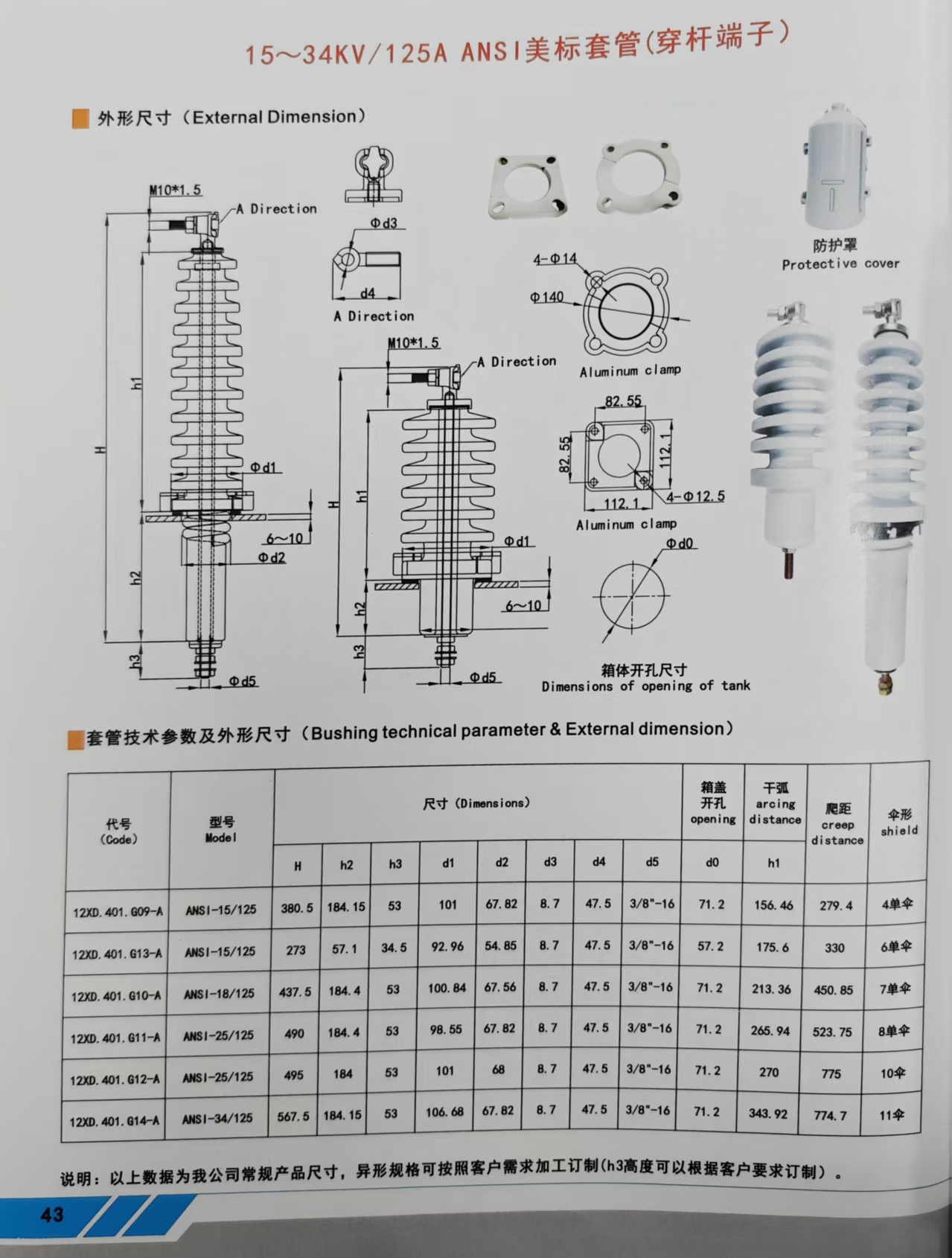
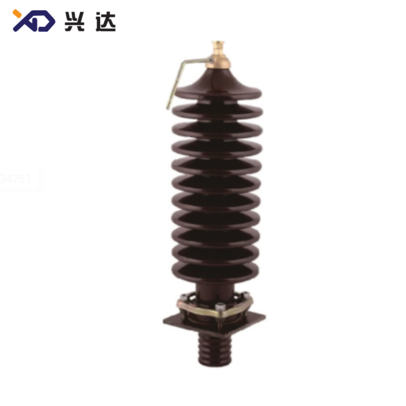
The complete bushing assembly consists of multi‑shed porcelain insulating housing, full‑length through conductive rod (through‑rod bushing connector), top connection hardware, aluminum clamping flange, protective cover and lower‑end threaded connection section. The multi‑umbrella‑shed porcelain structure increases creepage distance, strengthening anti‑pollution performance for outdoor service conditions. The aluminum clamp provides rigid mechanical mounting onto the transformer tank cover. The protective cover shields top‑end hardware from ultraviolet radiation, rain and airborne contaminants. The bottom threaded section connects directly to transformer internal windings.
Multiple shed configurations are available, ranging from 4‑shed up to 11‑shed variants. Models with higher creepage and arcing distances are selected for heavy‑pollution, coastal and high‑altitude sites. This bushing follows ANSI power‑equipment standards and supports interchangeability with mainstream ANSI‑series bushing products. Custom dimensional adjustments are permitted; for example, the h3 dimension can be modified according to specific project requirements. It is widely matched with pad‑mounted transformers, pole‑mounted distribution transformers and auxiliary transformers deployed in ANSI‑compliant power grids.
Core Advantages of 15‑34KV / 125A ANSI Bushing (Through‑rod bushing connector)
Through‑rod bushing connector for low‑resistance current transfer
The full‑length penetrating conductive rod removes extra intermediate contact points. It keeps stable low contact resistance under continuous 125A load current, greatly reducing risks of local overheating caused by loose contact interfaces. This design performs reliably for long‑time cyclic load variation.
ANSI Standard Compliance
Designed and dimensioned in accordance with ANSI specifications for medium‑voltage transformer bushings. It supports direct drop‑in replacement for existing ANSI‑spec bushings, suitable for new transformer manufacturing as well as field maintenance and spare‑part replacement work.
Multiple Porcelain Shed Combinations
Optional 4‑shed to 11‑shed porcelain housings provide adjustable creepage distance and arcing distance. Designers can select corresponding variants for ordinary inland locations, salt‑fog coastal regions, heavy‑industrial pollution zones and high‑altitude environments to lower external flash‑over failure probability.
Complete Supporting Mechanical Accessories
Equipped with aluminum clamping flange and protective cover. The aluminum clamp ensures stable mechanical fixation on transformer tank‑cover openings; the protective cover protects top‑end connection hardware against outdoor harsh weather erosion. All structural components are optimized to adapt to the internal operating environment of oil‑immersed transformers.
Excellent Electrical and Thermal Performance
Capable of enduring rated power‑frequency voltage, lightning impulse overvoltage, continuous 125A operating current and short‑circuit current impact. Optimized insulation coordination suppresses partial‑discharge risks under long‑term medium‑voltage operating cycles.
Flexible Customizable Dimensions
A full set of standard dimensional variants covers different overall height H, h2, h3 and diameter parameters. Tank‑opening dimensions are standardized to simplify transformer tank‑cover mechanical design for OEM manufacturers. Custom modification of h3 dimension and other non‑standard sizes can be realized to satisfy special project demands.
General Technical Specifications
General industry‑wide technical parameters for 15‑34KV / 125A ANSI Bushing (Through‑rod bushing connector). All dimension units: millimetre (mm).
| Code | Model | H | h2 | h3 | d1 | d2 | d3 | d4 | d5 | d0 | Arcing distance h1 | Creep distance | Umbrella shield |
|---|---|---|---|---|---|---|---|---|---|---|---|---|---|
| 12XD.401.G09‑A | ANSI‑15‑125 | 380.5 | 184.15 | 53 | 101 | 67.82 | 8.7 | 47.5 | 3/8"‑16 | 71.2 | 156.46 | 279.4 | 4‑shed |
| 12XD.401.G13‑A | ANSI‑15‑125 | 273 | 57.1 | 34.5 | 92.96 | 54.85 | 8.7 | 47.5 | 3/8"‑16 | 71.2 | 175.6 | 330 | 6‑shed |
| 12XD.401.G10‑A | ANSI‑18‑125 | 437.5 | 184.4 | 53 | 100.84 | 67.56 | 8.7 | 47.5 | 3/8"‑16 | 71.2 | 213.36 | 450.85 | 7‑shed |
| 12XD.401.G11‑A | ANSI‑25‑125 | 490 | 184.4 | 53 | 98.55 | 67.82 | 8.7 | 47.5 | 3/8"‑16 | 71.2 | 265.94 | 523.75 | 8‑shed |
| 12XD.401.G12‑A | ANSI‑25‑125 | 495 | 184 | 53 | 101 | 68 | 8.7 | 47.5 | 3/8"‑16 | 71.2 | 270 | 775 | 10‑shed |
| 12XD.401.G14‑A | ANSI‑34‑125 | 567.5 | 184.15 | 53 | 106.68 | 67.82 | 8.7 | 47.5 | 3/8"‑16 | 71.2 | 343.92 | 774.7 | 11‑shed |
Main Application Scenarios
Pad‑Mounted Distribution Transformers
Pad‑mount transformers widely deployed in North‑American distribution grids are one major application scenario. The through‑rod bushing connector delivers stable low‑resistance current transfer for outdoor cabinet‑type transformers, minimizing thermal risks under continuous load.
Pole‑Mounted Distribution Transformers
Pole‑mount transformers installed on utility poles face vibration caused by wind sway. The integrated through‑rod conductive structure avoids failure modes related to loose intermediate contacts, improving operational reliability for overhead power distribution equipment.
ANSI‑Standard New‑Energy Auxiliary Transformers
Distributed photovoltaic and wind‑power projects adopting North‑American transformer specifications frequently select this bushing. Its robust mechanical‑electrical performance adapts to complex outdoor weather conditions for renewable‑energy step‑down equipment.
On‑site Maintenance and Spare‑part Replacement
As an ANSI‑interchangeable component, this bushing is used for replacing aged or damaged medium‑voltage bushings within existing distribution networks. The standardized dimension set simplifies field fitting work for maintenance technicians.
Key Selection Guidelines
When specifying 15‑34KV / 125A ANSI Bushing (Through‑rod bushing connector), engineering and procurement teams should verify these critical parameters:
- Rated system voltage: Select 15 kV, 18 kV, 25 kV or 34 kV model matching actual grid operating voltage.
- Through‑rod bushing connector requirement: Confirm that through‑rod penetrating conductive structure is required for your transformer internal connection design.
- Creepage and arcing distance: Choose proper 4‑shed to 11‑shed configuration. Select higher‑shed‑count versions for coastal salt‑fog, industrial‑pollution and high‑altitude operating sites.
- Installation dimensions: Validate overall height H, h2, h3, diameter parameters and tank‑opening dimension d0, to ensure compatibility with transformer tank‑cover cut‑out. Note that h3 dimension supports custom modification.
- Operating environment: For high‑altitude, humid or corrosive atmospheres, upgrade to higher‑creepage‑distance shed configuration to compensate for degraded external insulation performance.
Installation & Operation Recommendations
- Complete visual inspection before installation. Check porcelain housing for cracks or chipping; inspect the through‑rod bushing connector for thread damage or surface scratches; verify integrity of aluminum clamp and protective cover parts.
- Place qualified sealing gasket between aluminum clamp flange and transformer tank cover. Tighten mounting bolts evenly in cross‑torque sequence to prevent transformer oil leakage.
- Complete internal connection between the bottom threaded end of through‑rod bushing connector and transformer winding conductors, ensure sufficient contact pressure.
- Finish external cable connection on the top‑end of through‑rod bushing connector, apply recommended fastening torque, avoid over‑torque damaging thread structure. Install the protective cover once cable connection is completed.
- After transformer oil filling, carry out insulation resistance test and corresponding high‑voltage tests before energized operation.
- Arrange periodic routine inspection during service: check flange sealing condition, porcelain shed surface contamination and connection‑point tightening status.
Common Potential Risks & Mitigation
Connection‑point overheating
Causes: insufficient fastening torque, oxidized contact surfaces. Mitigation: Clean contact surfaces before assembly; follow standard torque values; implement periodic re‑torque inspection.
Flange oil leakage
Causes: gasket aging, uneven bolt tightening torque, flange surface deformation. Mitigation: Use brand‑new qualified sealing gaskets; tighten mounting bolts in cross sequence; inspect flange flatness prior to installation.
Porcelain surface flash‑over
Causes: insufficient creepage distance for polluted environment, heavy dirt accumulation on porcelain sheds. Mitigation: Adopt higher‑shed‑count bushing for contaminated locations; carry out regular porcelain surface cleaning maintenance.
Mechanical damage to through‑rod bushing connector
Causes: impact during transportation and handling, excessive torque on top‑end threads. Mitigation: Protect bushing conductive rod against mechanical impact; strictly follow specified torque during cable fastening.
Conclusion
15‑34KV / 125A ANSI Bushing (Through‑rod bushing connector) is a key ANSI‑standard medium‑voltage insulating component for oil‑immersed distribution transformers. Its core advantage originates from the through‑rod bushing connector: the continuous penetrating conductive rod eliminates intermediate contact interfaces and realizes low‑resistance stable current transmission.
With multiple shed‑count options, standardized mounting dimensions and support for custom h3 dimension adjustment, this bushing is well‑suited for pad‑mounted, pole‑mounted and new‑energy auxiliary transformers under North‑American grid specifications. Proper model selection according to system voltage, pollution level and internal connection requirements, combined with standardized installation and regular maintenance, guarantees long‑term safe and stable operation. As global demand for ANSI‑style transformer equipment keeps growing, this through‑rod‑type bushing maintains important application value for medium‑voltage distribution projects.
Categories
Contact Us
Contact: Tianjin Delda Trading Co., Ltd
WhatsApp: +86 13662056855
Tel:
E-mail: solomon20210701@tjxddq.com
Add: Unit‑101, Workshop 3, Bozhong Automobile Industrial Park, No.5 Xianghui Road, Intersection of Xianghui Road and Gaoying Road, Beizhakou Town, Jinnan District, Tianjin, China