DIN Bushing
Complete Technical Guide for DIN‑Standard Transformer Porcelain Bushings
DIN Bushing: Full‑Technical Guide for DIN‑Standard Oil‑Immersed Transformer Bushings
Introduction
A DIN bushing is a metric‑dimensioned transformer feed‑through insulator originally defined under German DIN standards such as DIN 42530, DIN 42531 and DIN 42539, widely adopted across European power utilities, Middle‑East, African and Asian distribution‑transformer markets. Today most modern DIN‑pattern bushings comply with harmonized EN 50180, EN 50386 and IEC 60137 requirements while keeping the original DIN mechanical mounting footprints unchanged.
Its dual core function is to carry continuous load‑current through the earthed metallic transformer tank and provide stable dielectric insulation between live conductors and grounded tank structures. Unlike ANSI‑pattern bushings that use imperial dimensions and alternating‑shed porcelain geometry, classic DIN bushing designs apply uniform‑profile porcelain sheds, strict metric‑based flange‑bolt‑circle dimensions and standardized metric‑thread terminal connections. Low‑voltage DIN bushing variants (DIN 42539) serve transformer secondary terminals, while medium‑voltage DIN bushing models are deployed on primary sides for distribution‑class oil‑immersed transformers. Large volumes of DIN‑standard bushings are used as original‑equipment components as well as field‑replacement spare parts for transformer repair and retrofit projects.
This original industry‑focused article delivers universal technical definitions, structural breakdown, specification reference table, key engineering advantages, application constraints, typical failure modes and practical selection‑installation‑maintenance guidance. Optimized for Google indexing, this text can be directly published for industry blogs, technical directory pages and component‑knowledge libraries. No specific manufacturer or brand recommendation is included. Transformer design engineers, procurement specialists, field maintenance contractors and spare‑part buyers frequently search for DIN bushing dimensions, creepage‑distance values, interchangeability rules and troubleshooting guidance for tender specifications and on‑site repair workflows.
What is DIN Bushing for Oil‑Immersed Transformers
DIN bushing is a flange‑mounted feed‑through insulator family for oil‑filled transformers and reactors. Traditional DIN‑series standards have been superseded by European EN standards, yet the well‑established mechanical mounting dimensions remain dominant in global spare‑part markets. A complete DIN bushing assembly includes glazed‑porcelain insulator body, central copper‑alloy current‑carrying conductor, metric‑thread top terminals, flange‑sealing gaskets and fastening hardware. One portion of the bushing submerges inside mineral transformer oil, while the porcelain shed section operates under open‑air outdoor environmental conditions.
Two major DIN bushing categories dominate real‑world deployment:
- Medium‑Voltage DIN Bushing: Installed on transformer primary windings. It adopts uniform‑shed porcelain bodies, covers rated‑voltage classes from 6 kV up to 52 kV, and matches IEC lightning‑impulse‑withstand test requirements.
- Low‑Voltage DIN Bushing: Mainly governed by DIN 42539 standard, applied on transformer secondary output terminals. It supports very high continuous‑current ratings up to 6500 A for heavy‑duty distribution‑transformer applications.
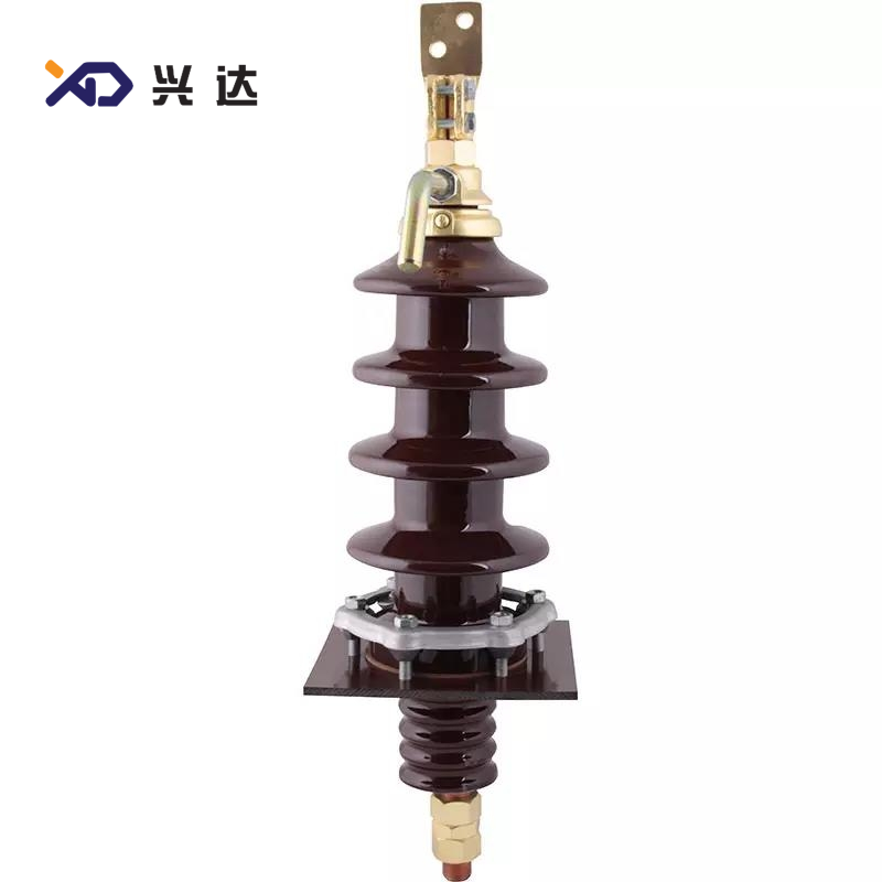
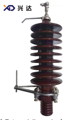
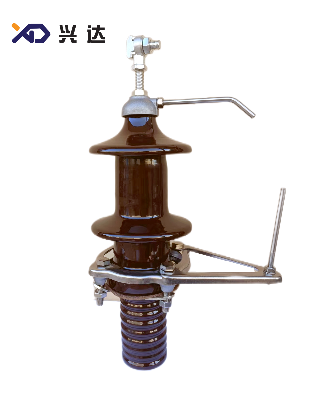
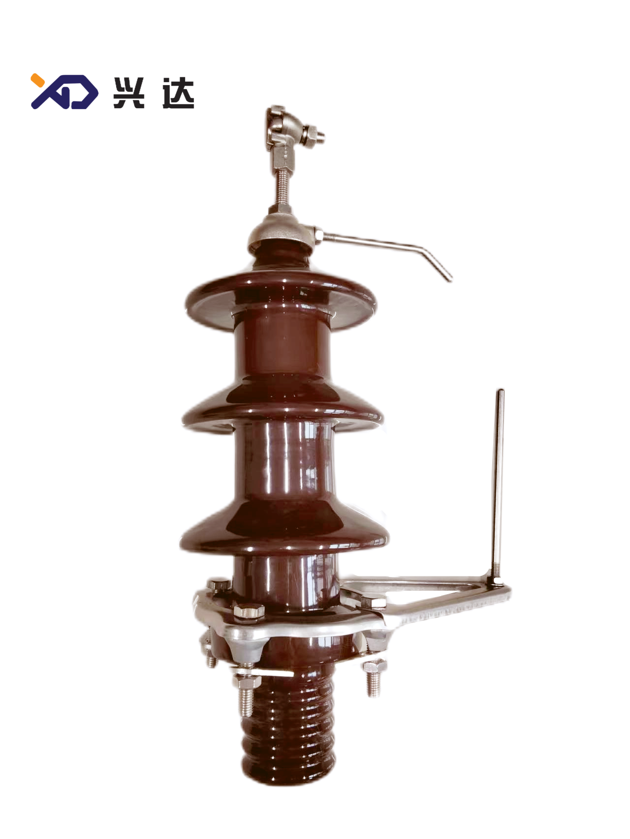
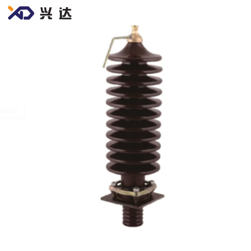
A recognizable structural characteristic of classic DIN‑pattern bushing is its uniform‑diameter shed profile: porcelain sheds share identical width dimensions, differing from ANSI‑type alternating‑wide‑narrow‑shed construction. Brown‑glazed porcelain is the most common standard color for DIN‑market applications. Most DIN bushings adopt fixed multi‑hole flange‑mounting structures with strictly standardized metric bolt‑circle diameters and metric‑size fasteners, which enables high‑level cross‑manufacturer mechanical interchangeability for qualified spare‑part units.
Core Structure of DIN Bushing
Each full DIN bushing assembly consists of these five key functional sub‑assemblies; every component directly influences long‑term field‑operation reliability:
- Uniform‑Shed Porcelain Insulator: High‑grade brown‑glazed electrical‑porcelain forms the outer weather‑proof housing. Uniform‑size sheds deliver defined creepage‑distance for pollution‑withstand performance and resist UV‑aging, frost damage and outdoor surface tracking. Enhanced‑creepage‑length variants are available for heavy‑pollution sites.
- Metric‑Standard Mounting Flange & Sealing Gasket: Flange units with fixed metric bolt‑hole layouts fasten the bushing onto transformer‑tank openings. Compressed nitrile‑rubber composite gaskets prevent transformer‑oil leakage and block moisture ingress into transformer‑oil cavities. Uneven bolt‑torque is one primary source of DIN bushing field‑sealing‑failure.
- Central Current‑Carrying Conductor: Solid copper‑alloy rod serves as the main conductive path. Conductor cross‑section is sized strictly according to rated‑continuous‑current to constrain temperature‑rise under full‑load and short‑circuit‑fault‑conditions.
- Metric‑Thread Top‑End Connection Terminal: Metric‑threaded stud terminals or flat‑bar connection lugs provide connection interfaces for external busbars and cable lugs. Thread specifications strictly follow metric‑system standards, which cannot be directly interchanged with imperial‑sized ANSI‑pattern terminals.
- Oil‑Immersed Lower Section: The lower bushing segment sits inside transformer insulating‑oil, delivering internal‑winding connection points and maintaining oil‑side dielectric‑performance. Certain high‑voltage DIN bushing versions include integrated internal‑shield structures for electric‑field optimization.
General Technical Specifications of DIN Bushing
The following table summarizes industry‑general parameter ranges for DIN‑standard transformer bushings. These reference values apply for specification review, tender‑document compilation and spare‑part‑replacement evaluation; actual project parameters must align with local utility‑standards and transformer‑design documentation.
| Parameter | Typical DIN Bushing Industry‑Standard Range | Critical Remarks |
|---|---|---|
| Rated Voltage Class | 1.2 kV ~ 52 kV | LV secondary and MV primary distribution‑transformer coverage; DIN 42530 / DIN 42539 for low‑voltage types |
| Rated Continuous Current | 250 A ~ 6500 A | Low‑voltage DIN bushing supports extra‑high‑current secondary‑terminal applications |
| Lightning Impulse Withstand Level (LIWL) | 60 kV, 95 kV, 125 kV, 250 kV | Defined by IEC 60137; equivalent to BIL concept within ANSI‑system specifications |
| Main Insulator Material | Brown‑glaze Electrical Porcelain; composite‑silicone optional | Uniform‑shed profile for classic DIN‑pattern units |
| Applicable Equipment | Oil‑immersed distribution transformers, power transformers, oil‑filled reactors | Mainly for European‑designed and export‑oriented transformer‑products |
| Ambient Operating Temperature | ‑40 °C ~ +55 °C | Covers cold‑winter European regions and tropical‑hot‑summer service territories |
| Maximum Service Altitude | ≤1000 m base rating; reinforced‑type up to 3000 m | Altitude‑derating required for installation above 1000 m elevation |
| Pollution‑Adaptation Creepage Distance | 16 mm/kV (light pollution) up to 31 mm/kV (very heavy pollution) | Extended‑creepage DIN bushing required for coastal salt‑fog and industrial‑pollution zones |
| Terminal Configuration | Metric‑thread stud terminals, flat‑bar lugs | Strict metric‑thread specification; non‑interchangeable with imperial‑ANSI terminals |
| Mounting Pattern | Fixed‑flange mounting with metric bolt‑circle dimensions | 4‑hole or 6‑hole flange layouts, strictly metric‑dimensioned for interchangeability |
| Porcelain‑Body Standard Glaze Color | Brown | Default visual specification for DIN‑market transformer accessories |
Key Advantages of DIN‑Standard Transformer Bushings
Transformer OEMs, utility‑asset‑operators and maintenance teams select DIN bushing solutions for multiple practical engineering benefits oriented toward European‑style power‑grid infrastructure.
1. High‑Degree Mechanical Interchangeability via Strict Metric‑Standardization
DIN bushing follows rigid metric‑dimension specifications for flange bolt‑circles, mounting‑hole layouts and terminal‑thread sizes. Qualified DIN‑pattern spare‑part units fit existing transformer‑tank flange openings without custom modification work during replacement‑maintenance. Standardized dimensional‑tolerances reduce engineering‑verification workload for OEM‑design‑teams and simplify global spare‑part‑procurement workflows.
2. Mature Standard‑System Backed by IEC / EN Harmonization
Original DIN‑series documents have evolved into modern EN and IEC international‑standards frameworks. DIN‑pattern bushing products comply with IEC 60137 test‑requirements covering dielectric‑performance, thermal‑cycle‑testing, partial‑discharge‑limits and mechanical‑strength‑verification. This unified‑standard‑background supports cross‑border project acceptance for export‑oriented transformer‑manufacturers.
3. Wide‑Range Current‑Rating Coverage for LV‑Side Heavy‑Current Scenarios
Low‑voltage DIN bushing (DIN 42539) supports extremely high‑continuous‑current ratings up to 6500 A, perfectly matching large‑capacity distribution‑transformer secondary‑terminal heavy‑current‑output‑demands. Multiple‑current‑grade options enable precise component‑selection according to transformer‑rated‑output‑current without over‑specification‑waste.
4. Proven Mechanical‑Dielectric Reliability for Global Outdoor Deployment
High‑quality brown‑glazed porcelain‑insulator delivers excellent anti‑ultraviolet‑aging, frost‑resistance and mechanical‑shock‑resistance performance. Properly‑sized central‑conductor‑structures keep temperature‑rise within permitted‑limits under rated‑continuous‑current‑operation. Qualified DIN‑bushes withstand specified short‑time thermal‑and‑dynamic‑current‑stress during power‑network‑short‑circuit‑fault‑events. Extended‑creepage‑length variants can be specified for coastal‑salt‑fog and heavy‑industrial‑pollution‑environments.
5. Diverse‑Sourcing Base for Global‑Spare‑Part Logistics
DIN‑compliant transformer‑bushings enjoy wide‑popularity within European, African, Middle‑East and many Asian‑power‑markets. Standard‑model DIN‑bushing spare‑parts are stocked by transformer‑repair‑workshops and utility‑warehouses across multiple‑regions. Mature‑global‑supply‑chains shorten spare‑part‑delivery‑cycles and support emergency‑repair‑response for grid‑fault‑incidents.
Critical Operating Constraints for DIN Bushing
All DIN bushing electrical‑mechanical‑performance indexes are defined under standard‑reference‑operating‑conditions. Deviations from reference‑conditions require performance‑derating or enhanced‑specification‑component‑selection.
- Altitude‑derating‑requirement: When installation‑altitude exceeds 1000 m, air‑dielectric‑strength decreases. Operators shall apply insulation‑level‑derating or select high‑altitude‑reinforced‑type DIN bushing.
- Pollution‑level‑matching: Standard‑creepage‑DIN bushing applies for inland‑light‑pollution‑regions. For coastal‑salt‑fog‑zones and chemical‑plant‑surrounding heavy‑pollution‑sites, long‑creepage enhanced‑DIN bushing must be adopted, otherwise surface‑leakage‑current and flash‑over‑failure‑rises sharply under wet‑weather‑conditions. Classic uniform‑shed‑profile shows relatively weaker water‑cascade‑interruption‑capacity compared with ANSI‑alternating‑shed‑design under heavy‑rainfall‑conditions.
- No‑direct‑interchange‑with‑ANSI‑bushing: DIN‑metric‑flange‑and‑terminal‑geometry cannot directly fit ANSI‑designed‑transformer‑tank‑bushing‑well‑openings. Retrofit‑replacement requires custom‑adapter‑plate‑modification and full‑internal‑clearance‑verification.
- Cantilever‑force‑restriction: External‑connected‑cables‑and‑busbars shall not transmit excessive‑cantilever‑mechanical‑load onto DIN‑bushing‑terminals. Over‑large‑cantilever‑force‑may trigger‑porcelain‑micro‑cracks and hidden‑insulation‑dangers.
Common Failure Modes of DIN Bushing
Understanding typical DIN bushing failure‑modes helps maintenance‑teams‑carry‑out‑predictive‑maintenance‑work‑and‑avoid‑unexpected‑transformer‑forced‑outages.
Oil‑Leakage at Flange‑Gasket‑Interface
Oil‑seepage‑at‑sealing‑gasket‑positions‑represents‑one‑of‑the‑most‑frequently‑observed‑DIN‑bushing‑faults. Root‑causes‑include‑aging‑composite‑gaskets,‑uneven‑clamping‑bolt‑torque,‑deformed‑flange‑mating‑surfaces,‑foreign‑particle‑residues‑trapped‑in‑sealing‑interfaces‑or‑mechanical‑shock‑during‑transportation‑assembly.‑Even‑minor‑oil‑seepage‑creates‑access‑channels‑for‑moisture‑to‑enter‑transformer‑tank‑interiors‑and‑degrades‑insulating‑oil‑dielectric‑strength.
Surface‑Flash‑over‑and‑Pollution‑Tracking
Salt‑dust,‑industrial‑deposit‑and‑bird‑dropping‑accumulate‑on‑porcelain‑shed‑surfaces.‑When‑dew‑or‑rain‑wets‑contaminated‑insulator‑surfaces,‑surface‑leakage‑current‑increases‑and‑may‑trigger‑surface‑flash‑over.‑Repeated‑flash‑over‑events‑generate‑carbon‑tracking‑paths‑on‑porcelain‑glaze‑layers‑and‑permanently‑degrade‑bushing‑insulation‑capacity.‑Classic‑uniform‑shed‑design‑of‑DIN‑bushing‑is‑more‑vulnerable‑to‑continuous‑rain‑water‑film‑formation‑under‑heavy‑rain‑without‑adequate‑creepage‑margin.
Over‑heating‑at‑Thread‑Terminal‑Connection‑Points
Excessive‑contact‑resistance‑at‑DIN‑metric‑thread‑terminals‑originates‑from‑loose‑bolt‑fastening,‑poor‑contact‑surface‑treatment‑or‑galvanic‑corrosion‑between‑dissimilar‑metals.‑High‑contact‑resistance‑generates‑serious‑Joule‑heating‑under‑load‑current;‑temperature‑rise‑further‑oxidizes‑contact‑surfaces‑and‑forms‑vicious‑circles.‑Severe‑cases‑produce‑terminal‑burn‑loss‑and‑transformer‑forced‑shutdown.
Porcelain‑Body‑Micro‑Crack‑and‑Hidden‑Insulation‑Risk
Transport‑collision,‑improper‑handling,‑seismic‑vibration‑or‑excessive‑cantilever‑force‑may‑produce‑invisible‑micro‑cracks‑on‑DIN‑bushing‑porcelain‑bodies.‑Hidden‑cracks‑do‑not‑trigger‑immediate‑failure,‑yet‑will‑gradually‑expand‑under‑temperature‑cycling‑and‑transformer‑oil‑pressure‑variation,‑eventually‑leading‑to‑sudden‑oil‑leakage‑or‑dielectric‑breakdown‑faults‑in‑service.
Moisture‑Induced‑Internal‑Insulation‑Degradation
When‑gasket‑sealing‑fails‑or‑porcelain‑cracks‑occur,‑humid‑outside‑air‑and‑water‑vapor‑penetrate‑into‑transformer‑tank‑interiors.‑Moisture‑contaminates‑transformer‑oil‑and‑weakens‑insulation‑performance.‑Long‑term‑moisture‑invasion‑triggers‑partial‑discharge‑phenomena‑inside‑insulation‑structures,‑gradually‑erodes‑insulating‑materials‑and‑finally‑causes‑catastrophic‑breakdown‑accidents.
DIN Bushing Selection Checklist
When‑specifying‑or‑replacing‑DIN‑bushing‑for‑oil‑immersed‑transformers,‑verify‑these‑technical‑items‑item‑by‑item‑to‑prevent‑specification‑mismatch‑risks:
- Confirm‑rated‑voltage‑class‑and‑lightning‑impulse‑withstand‑level‑strictly‑matching‑transformer‑winding‑insulation‑requirements.‑Impulse‑withstand‑value‑is‑critical‑for‑lightning‑surge‑protection.
- Match‑rated‑continuous‑current‑with‑transformer‑maximum‑operating‑current‑and‑reserve‑reasonable‑overload‑margin,‑especially‑for‑low‑voltage‑heavy‑current‑DIN‑bushing‑models.
- Confirm‑mechanical‑mounting‑specifications:‑flange‑bolt‑circle‑diameter,‑bolt‑hole‑quantity‑and‑size,‑terminal‑metric‑thread‑specification‑and‑oil‑immersed‑insertion‑depth.‑Voltage‑and‑current‑parameters‑alone‑cannot‑guarantee‑mechanical‑fit‑during‑replacement‑procurement.
- Evaluate‑site‑operating‑environment:‑installation‑altitude,‑pollution‑severity,‑coastal‑salt‑fog‑level‑and‑ambient‑temperature‑range;‑judge‑whether‑extended‑creepage‑or‑high‑altitude‑reinforced‑DIN‑bushing‑is‑required.
- Confirm‑terminal‑type‑(metric‑thread‑stud‑or‑flat‑bar‑lug)‑according‑to‑field‑cable‑busbar‑connection‑scheme.
- Restrict‑external‑cantilever‑load‑value‑to‑avoid‑porcelain‑mechanical‑stress‑damage.
- Cross‑reference‑local‑utility‑acceptance‑test‑standards‑and‑relevant‑IEC/EN‑norms‑for‑tender‑project‑procurement.
Installation & Maintenance Best Practices for DIN Bushing
Standardized‑installation‑and‑periodic‑maintenance‑work‑effectively‑extend‑DIN‑bushing‑service‑life‑and‑reduce‑transformer‑failure‑probability.
Installation Guidelines
- Complete‑full‑visual‑inspection‑before‑installation:‑check‑porcelain‑body‑for‑cracks,‑chipping‑or‑glaze‑damage;‑inspect‑gaskets,‑thread‑terminals‑and‑flange‑hardware‑for‑deformation‑or‑corrosion.‑Reject‑all‑visibly‑damaged‑units.
- Thoroughly‑clean‑transformer‑tank‑flange‑mating‑surfaces‑and‑bushing‑sealing‑faces;‑remove‑old‑gasket‑residues,‑metal‑burrs‑and‑foreign‑debris.
- Apply‑brand‑new‑matched‑specification‑compression‑gaskets.‑Re‑using‑aged‑gaskets‑is‑strictly‑prohibited.
- Tighten‑flange‑bolts‑following‑cross‑symmetrical‑torque‑sequence‑and‑strictly‑follow‑recommended‑torque‑values.‑Under‑torque‑triggers‑oil‑leakage;‑over‑torque‑risks‑porcelain‑cracking.
- Control‑external‑cable‑busbar‑pulling‑force,‑prohibit‑transmitting‑excessive‑cantilever‑mechanical‑stress‑to‑bushing‑terminals.
- Complete‑static‑oil‑leakage‑inspection‑before‑transformer‑energization.
Routine‑Maintenance Suggestions
- Periodic‑visual‑inspection:‑check‑oil‑leakage‑traces‑around‑flange‑gasket‑interfaces,‑porcelain‑shed‑pollution‑degree,‑porcelain‑crack‑signs‑and‑thread‑terminal‑over‑heating‑discoloration.
- For‑heavy‑pollution‑coastal‑sites,‑schedule‑regular‑porcelain‑surface‑cleaning‑work‑to‑reduce‑surface‑flash‑over‑risk.‑Pay‑extra‑attention‑to‑uniform‑shed‑surface‑pollution‑accumulation.
- Apply‑thermal‑imaging‑inspection‑under‑transformer‑load‑condition‑to‑detect‑abnormal‑hot‑spots‑on‑terminal‑connection‑positions;‑resolve‑bad‑contact‑faults‑timely.
- During‑transformer‑overhaul‑cycles,‑replace‑aging‑sealing‑gaskets‑even‑if‑no‑obvious‑oil‑leakage‑appears.
- Store‑spare‑DIN‑bushing‑units‑inside‑dry‑covered‑warehouses;‑avoid‑long‑term‑outdoor‑stacking‑exposed‑to‑rain‑and‑salt‑mist.
Conclusion
DIN bushing‑occupies‑an‑irreplaceable‑component‑position‑within‑European‑style‑oil‑immersed‑distribution‑transformer‑systems.‑As‑the‑critical‑insulation‑conduction‑interface‑linking‑transformer‑internal‑windings‑and‑external‑power‑networks,‑its‑reliable‑performance‑directly‑determines‑transformer‑asset‑safety‑and‑grid‑operating‑stability.
During‑DIN‑bushing‑specification‑and‑replacement‑procurement‑phases,‑technical‑teams‑cannot‑focus‑merely‑on‑voltage‑and‑current‑ratings.‑Engineers‑must‑pay‑sufficient‑attention‑to‑lightning‑impulse‑withstand‑rating,‑metric‑flange‑mounting‑geometry,‑terminal‑thread‑specification,‑site‑environmental‑parameters,‑gasket‑sealing‑system‑design‑and‑standardized‑installation‑process‑requirements.‑Mastering‑common‑failure‑modes‑and‑executing‑standardized‑installation‑maintenance‑workflows‑can‑effectively‑reduce‑avoidable‑transformer‑outage‑incidents.
With‑continuous‑construction‑and‑asset‑retrofit‑of‑European,‑Middle‑East‑and‑African‑power‑grids‑adopting‑DIN‑system‑equipment,‑proper‑specification,‑quality‑control‑and‑field‑application‑of‑DIN‑standard‑transformer‑bushings‑remain‑important‑technical‑topics‑for‑transformer‑design‑engineers,‑OEM‑procurement‑teams‑and‑power‑utility‑maintenance‑departments.
Categories
Contact Us
Contact: Tianjin Delda Trading Co., Ltd
WhatsApp: +86 13662056855
Tel:
E-mail: solomon20210701@tjxddq.com
Add: Unit‑101, Workshop 3, Bozhong Automobile Industrial Park, No.5 Xianghui Road, Intersection of Xianghui Road and Gaoying Road, Beizhakou Town, Jinnan District, Tianjin, China