Oil Level Indicator

Oil Level Indicator – Complete Technical Guide for Oil‑Immersed Transformers
Oil Level Indicator – Complete Technical Guide for Oil‑Immersed Transformers
What is an Oil Level Indicator
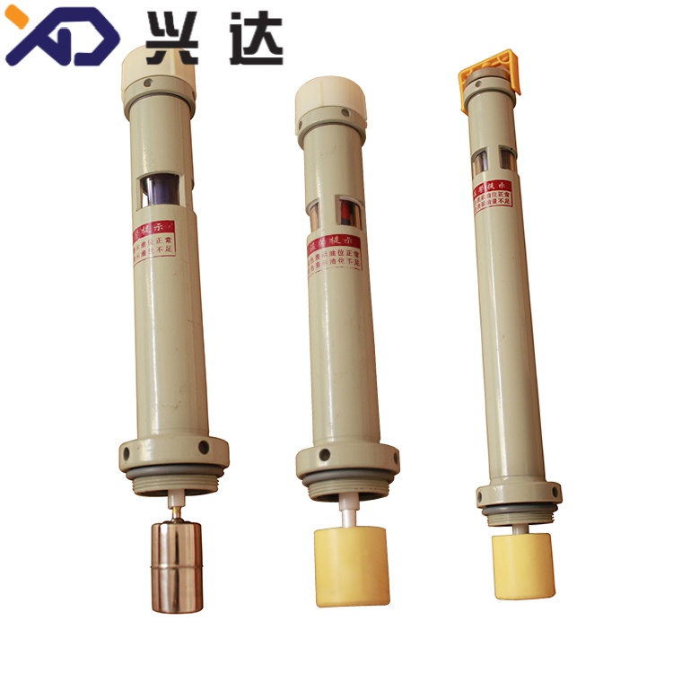
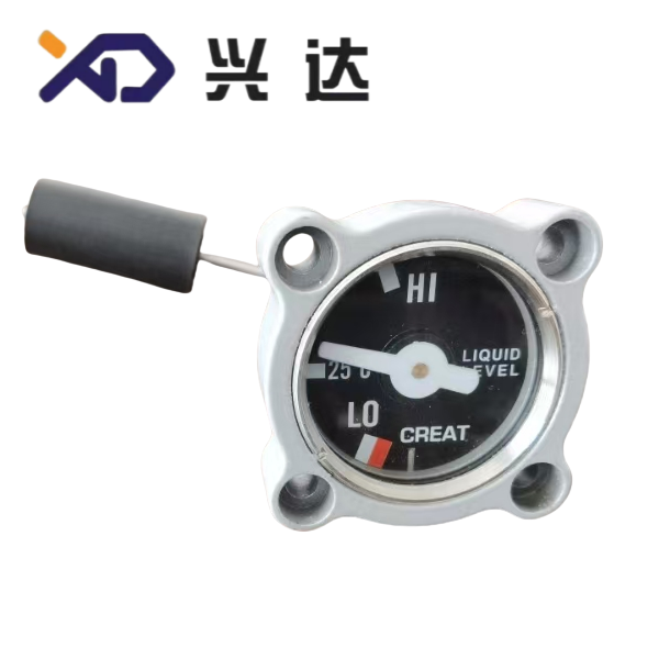
An oil level indicator (also widely known as transformer oil level gauge) is an essential auxiliary measuring instrument fitted on the oil conservator (expansion tank) or auxiliary compartments of oil‑immersed transformers and reactors. Its core mission is to visually display real‑time mineral insulating‑oil volume changes caused by thermal expansion and contraction, while providing electrical alarm or trip signals for abnormal high‑level and low‑level conditions.
Transformer insulating oil expands when temperature rises under heavy load and shrinks when temperature drops under light‑load or cold ambient conditions. Without reliable oil‑level monitoring, hidden risks appear: excessively low oil level may expose winding insulation to air, causing partial discharge, insulation aging and internal breakdown. Over‑high oil level reduces gas buffer space inside conservator, raising internal tank pressure and potentially triggering oil leakage or safety‑valve activation.
Magnetic‑coupling float‑type oil‑level indicators are the dominant mainstream for distribution and power transformers. The internal float follows oil‑surface height; magnetic‑force transmits motion to the external dial pointer without mechanical shaft penetration through the tank wall. This magnetic‑isolation design eliminates potential oil‑leakage points at shaft‑gland seals. Some models integrate built‑in micro‑switches / reed‑switch alarm contacts; high‑end versions add 4‑20 mA analog output for remote SCADA system monitoring.
Major applicable international standards include IEC 60076‑22‑1 for transformer fittings, IEEE C57.12.10 for North‑American transformer requirements, covering mechanical performance, contact rating and environmental adaptability for oil‑level measuring devices.
Main Types of Transformer Oil Level Indicators & Comparative Overview
Different construction principles serve various‑grade transformers, from small distribution‑transformer conservators up to large substation power‑transformers and independent OLTC tap‑changer oil compartments.
| Type | Working Principle | Core Feature | Typical Application |
|---|---|---|---|
| Magnetic float‑type oil level indicator | Internal float drives external dial pointer via magnetic coupling; no penetrating shaft | Local visual dial, optional alarm contacts; sealed anti‑leakage structure | Oil conservator for distribution & medium‑size power transformers (most‑common type) |
| Sight‑glass / prismatic level gauge | Direct visual observation through tempered‑glass window | Pure local visual reading, no electrical signal output | Small sealed transformers, auxiliary oil chamber local inspection |
| Magnetostrictive oil level transmitter | Magnetostrictive sensor detects float position, outputs analog signal | High‑precision continuous remote signal; no mechanical gear wear | Large power transformers, smart‑grid online asset monitoring |
| Capacitive oil‑level sensor | Capacitance value changes according to oil immersion depth | No moving mechanical float parts; high shock‑resistance | OLTC independent oil compartment, compact sealed equipment |
Important note: Sight‑glass gauges have limited functionality. They cannot deliver remote alarm signals and carry risk of glass cracking, so they are mostly used as secondary auxiliary observation instead of primary monitoring device on critical‑mission transformers. Magnetic float‑type indicators are preferred for standard conservator installations.
Key Technical Specification Parameters
Below table collects general industry‑typical parameters for transformer‑grade oil‑level indicators, supporting procurement and engineering specification writing.
| Parameter | Unit | Practical Explanation |
|---|---|---|
| Dial diameter | mm | Larger dial improves ground‑level visual readability for substation sites |
| Operating ambient temperature | °C | Adapt to outdoor tropical, temperate and cold‑climate field conditions |
| Medium (transformer oil) temperature | °C | Matches normal operating temperature range of mineral insulating oil |
| Alarm contact configuration | — | Options: high‑oil‑level alarm, low‑oil‑level alarm, low‑level trip function |
| Contact rated capacity | V‑A | Control‑circuit signal output for alarm relay or PLC input |
| Remote signal output (optional) | mA | Standard analog signal for remote SCADA monitoring system |
| Mounting installation | — | Matching flange dimensions follow IEC or ANSI / NPT requirements |
| Compliance standard | — | Transformer accessory performance and test standard |
| Protection class | — | Outdoor weather‑proof, dust‑proof housing for substation environment |
Specification reminder: The dial scale shall match the actual volume curve of the target conservator, instead of using generic 0‑100 % uniform scale. Oil‑level variation correlates strongly with oil temperature change for transformer conservators.
Core Performance Advantages of Magnetic Float‑Type Oil‑Level Indicator
- Zero‑penetration magnetic‑coupling sealing designPower transmission purely relies on magnetic force crossing the conservator metal wall. There is no rotating mechanical shaft piercing through tank shell, removing one major source of mineral‑oil leakage risk which troubles traditional shaft‑driven level gauges.
- Combined local indication and multi‑point alarm functionOn‑site staff can directly read oil‑level status from dial pointer without opening tank housing. Pre‑set contacts trigger alarm signals for high‑oil‑level and low‑oil‑level conditions, reminding operation‑maintenance teams of oil leakage, over‑filling or breathing‑system failure at early stage. Some configurations support trip‑contact output for critical‑protection interlock.
- Wide environmental adaptability for outdoor deploymentWeather‑resistant die‑cast metal housing provides dust, rain and UV‑ray resistance, suitable for pole‑mounted, pad‑mounted and substation transformers exposed to wind, rain, coastal salt spray and industrial polluted atmosphere.
- Optional remote monitoring capabilityUnits equipped with 4‑20 mA transmitter convert float position into continuous analog signal. Operators monitor oil‑level trend remotely inside control room; trending data helps discover slow oil‑leakage by tracking gradual level drop over weeks, before severe fault occurs.
- Modular standardized mechanical interfaceMultiple flange sizes are available for IEC DIN metric and ANSI imperial conservator designs. Float‑arm length can be adjusted to adapt different conservator internal depth, simplifying assembly for transformer manufacturers.
Common Failure Modes, Root‑Cause Analysis & Counter‑Measures
Field statistics show most oil‑level indicator malfunctions stem from improper installation, transportation damage or aging instead of raw manufacturing defects.
| Failure Phenomenon | Probable Root Cause | Recommended Counter‑Measure |
|---|---|---|
| Pointer stuck, no response to oil‑level change | Float arm jammed by metal debris or oil sludge; bent pendulum rod; strong external magnetic interference | De‑energize transformer, remove indicator assembly; clean foreign debris; repair or replace deformed float arm; eliminate nearby magnetic sources |
| Dial reading inconsistent with real oil level | Float chamber water ingress / float sinking; incorrect float‑arm length mismatching conservator dimension; magnetic coupling weakening | Inspect float for leakage damage; adjust float‑arm dimension strictly according to conservator drawing; calibrate or replace complete unit |
| False or intermittent alarm triggering | Reed‑switch magnet position offset; heavy mechanical vibration on conservator | Readjust alarm trigger‑magnet location; add vibration‑damping measures for mounting base; inspect wiring terminals for looseness |
| No 4‑20 mA remote signal output | Auxiliary power‑supply deviation; loose terminal wiring; internal transmitter failure | Verify 24 V DC power supply; tighten wiring terminals; test transmitter output signal with multimeter |
Safety reminder: All disassembly work for oil‑level indicators must be performed after transformer power‑off, grounding and lock‑out‑tag‑out procedure, to prevent pressure‑spray of hot insulating‑oil.
Practical Selection Guidance for Transformer Design & Procurement
Four key factors should be confirmed during component specification phase:
- Installation environment & conservator geometryConfirm conservator internal depth, flange mounting dimension (metric IEC‑flange or ANSI NPT thread), outdoor or indoor service condition, salt‑spray / high‑altitude pollution grade. Select corresponding IP‑grade housing.
- Signal‑function requirement definitionFor basic local inspection only: choose indicator with visual dial plus high / low alarm contacts. For substation smart‑grid projects requiring remote monitoring: add 4‑20 mA analog‑output module. Independent OLTC oil compartments normally require compact small‑size oil‑level indicator separately, do not share main conservator gauge reading.
- Contact configuration definitionClarify number and purpose of SPDT contacts: low‑level alarm, high‑level alarm, low‑level protection trip. Confirm contact voltage‑ampere rating matches control‑circuit design.
- Compliance documentsSpecify reference standard IEC 60076‑22‑1 or IEEE C57.12.10. Request factory test report covering magnetic‑coupling performance, contact operation test, environmental aging test.
Installation, Commissioning & Preventive‑Maintenance Guidelines
Installation key points
- Mount oil‑level indicator vertically within ±5° tolerance; tilted installation causes float mechanical friction and inaccurate readings.
- Adjust float‑arm length strictly according to conservator drawing. Do not arbitrarily shorten or extend float rod.
- Complete all wiring work of alarm‑signal terminals before sealing terminal box; guarantee cable‑gland sealing for outdoor application to stop moisture entering.
- After installation, manually simulate float movement to verify pointer rotation and alarm‑contact trigger function before transformer oil‑filling.
Periodic maintenance items
General inland environment: inspect once every 2‑3 yearsCoastal salt‑spray / heavy‑polluted area: inspect once per 1 year
- Visual inspection: check dial pointer reading, housing corrosion status, terminal‑box sealing integrity.
- Check alarm‑contact function by simulation test during transformer overhaul.
- Verify remote 4‑20 mA output value compares consistently with local dial indication.
Check for mechanical pointer sticking phenomenon. Replace worn‑out units if pointer jams or readings drift significantly.
Conclusion
Oil‑level indicator is a simple but vital conservator fitting for oil‑immersed transformers. Magnetic float‑type oil‑level indicators dominate worldwide for combining local visual reading, multi‑point alarm contacts and optional remote analog signal output. Improper specification selection, tilted installation or neglected periodic maintenance will create false readings and hidden transformer risks.
Transformer designers and procurement teams must match flange dimension, float‑arm length, contact configuration and environmental protection grade to actual conservator and project requirements. Combined with standardized installation and cyclic maintenance, oil‑level indicators provide reliable early warning for oil‑leakage, over‑filling and breathing‑system faults, protecting long‑term safe service life of distribution and power transformers.
PREVIOUS:Oil level indicator NEXT:Oil level indicator
Categories
Contact Us
Contact: Tianjin Delda Trading Co., Ltd
WhatsApp: +86 13662056855
Tel:
E-mail: solomon20210701@tjxddq.com
Add: Unit‑101, Workshop 3, Bozhong Automobile Industrial Park, No.5 Xianghui Road, Intersection of Xianghui Road and Gaoying Road, Beizhakou Town, Jinnan District, Tianjin, China