Flat iron core
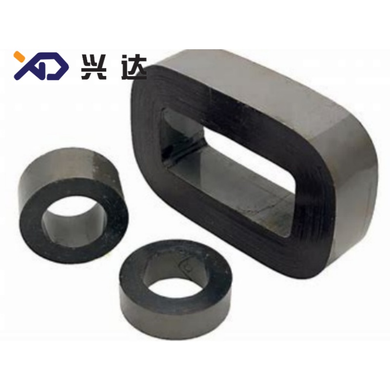
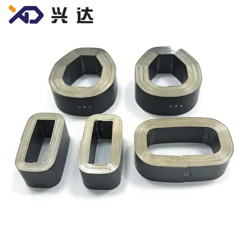
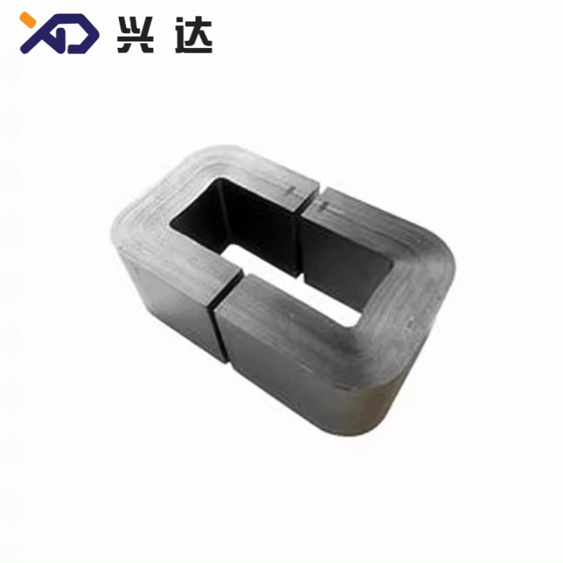
Flat Iron Core of CRGO Silicon Steel for Oil‑Immersed Distribution Transformer
Flat Iron Core: Complete Technical Guide for Distribution Transformer Magnetic Components
Introduction
What is Flat Iron Core
The production workflow starts from continuous CRGO silicon‑steel coil. Raw strips are cut to target width, bent into rectangular frames through automated bending equipment, stacked to required core cross‑section thickness, then annealed to eliminate mechanical stress generated during cutting and bending processes. Stress‑relief annealing restores original magnetic permeability and reduces extra loss caused by mechanical deformation. After annealing, core frames are clamped and fastened by non‑magnetic structural hardware to maintain stable mechanical tightness during long‑term transformer operation.
- Closed flat iron core: Fully continuous frame without cutting joints, minimum magnetic reluctance, excellent low‑loss performance, widely used for new‑build high‑efficiency distribution transformers.
- Open‑joint flat iron core: Pre‑bent flat frames with separable joints, convenient for direct installation over pre‑fabricated transformer coils, suitable for aftermarket replacement and transformer refurbishment projects.
Main Raw Material for Flat Iron Core
- Core material: Cold‑rolled grain‑oriented silicon steel (CRGO). Common sheet thickness includes 0.23 mm, 0.27 mm, 0.30 mm, 0.35 mm. Lower thickness brings better loss‑reduction performance with higher material cost.
- Surface insulation: Inorganic insulating coating on silicon‑steel sheet surface, isolating each lamination layer to suppress eddy‑current loss inside core assembly.
- Fastening hardware: Non‑magnetic clamping bands and brackets, preventing short‑circuit between silicon‑steel layers and avoiding magnetic shunt loss.
Typical Application Scenarios of Flat Iron Core
- Oil‑immersed distribution transformers for utility power grid (10 kV, 20 kV voltage classes)
- Industrial plant power transformers, commercial building power supply transformers
- Renewable energy step‑up transformers for solar and wind power stations
- Single‑phase pole‑mounted distribution transformers for rural power networks
- Transformer retrofitting and spare‑part replacement projects
- Medium‑capacity special transformers for mining, water treatment and manufacturing workshops
Important note: Flat iron core is designed for 50 Hz / 60 Hz power‑frequency transformer equipment. It shall not be applied for high‑frequency switching‑mode power supplies; ferrite cores are the correct solution for high‑frequency working conditions. Flat iron core cannot directly replace 3D wound core, as mechanical dimension and three‑phase magnetic circuit symmetry differ significantly between two core structures.
Technical Parameter Reference Table for Flat Iron Core
| Transformer Rated Capacity | Suggested Silicon‑Steel Thickness | Typical No‑Load Loss Reference | Core Frame Type | Phase Type | Main Application |
|---|---|---|---|---|---|
| 30 kVA‑100 kVA | 0.27 mm / 0.30 mm | 70 W‑140 W | Open‑joint flat frame | Single‑phase / Three‑phase | Small‑size pole‑mounted distribution transformer |
| 125 kVA‑250 kVA | 0.27 mm | 160 W‑280 W | Closed flat frame | Three‑phase | General‑purpose grid distribution transformer |
| 315 kVA‑630 kVA | 0.23 mm / 0.27 mm | 320 W‑540 W | Closed flat frame | Three‑phase | Urban and industrial distribution transformer |
| 800 kVA‑1250 kVA | 0.23 mm | 620 W‑850 W | Multi‑frame closed flat core | Three‑phase | Medium‑capacity substation transformer |
| 1600 kVA‑2500 kVA | 0.23 mm | 1000 W‑1400 W | Multi‑frame closed flat core | Three‑phase | Large‑capacity industrial distribution transformer |
| Custom non‑standard capacity | 0.23‑0.35 mm | Project‑dependent | Open‑joint or closed flat frame | Single‑phase / Three‑phase | Special‑spec transformer and retrofit project |
Key Advantages of Qualified Flat Iron Core
- Reduced no‑load loss and no‑load current: Compared with traditional manually stacked laminated core, flat iron core minimizes air gaps at magnetic joints. Well‑manufactured closed flat iron core can cut no‑load current by 60‑80 % and lower no‑load loss by 20‑35 %, realizing long‑term energy saving for power‑grid transformers running 24‑7 all year round.
- Low‑noise operation: Continuous flat frame structure reduces magnetic vibration and magnetostriction noise. Properly clamped flat iron core helps transformer unit achieve low acoustic noise performance, suitable for residential area and urban substation installation.
- Flexible dimension customization: Flat planar frame structure supports custom‑made core window height, limb width and yoke size. Engineers can adjust core geometry to match different winding dimensions, tank outlines and overall transformer layout requirements.
- Improved mechanical stability: Integrated flat frame structure enhances core integral rigidity. After proper clamping, the flat iron core resists vibration during transportation and normal operation, lowering risk of loose silicon‑steel sheets and internal short‑circuit faults.
- Convenient assembly options: Open‑joint flat iron core frames can be fitted over pre‑wound coils, simplifying production workflow for transformer refurbishment and spare‑part replacement. Closed‑type flat iron core delivers maximum magnetic performance for new‑build transformer manufacturing.
Cost‑balanced performance: Flat iron core achieves most energy‑saving benefits of wound‑core technology without the high production difficulty of full 3‑dimensional wound cores. It provides a practical middle‑ground solution for global transformer markets.
Core Selection Guidelines for Flat Iron Core
- Silicon‑steel grade and thickness selection: For high‑efficiency energy‑saving transformers, prioritize 0.23 mm low‑loss CRGO flat iron core. For cost‑sensitive conventional projects, 0.27 mm or 0.30 mm grade is acceptable. Avoid ordinary non‑oriented silicon steel for power‑frequency distribution transformer flat iron core, as it will generate excessive iron loss.
- Select closed‑type or open‑joint structure: Closed flat iron core is recommended for new‑manufactured transformers pursuing optimal magnetic performance. Open‑joint flat iron core fits maintenance and retrofit scenarios where coils are already completed.
- Stress‑relief annealing requirement: Cutting and bending will produce internal mechanical stress inside silicon‑steel sheets. Flat iron core without annealing treatment will suffer sharp increase of no‑load loss. Always confirm annealing procedure is completed for selected flat iron core components.
- Clamping and fastening requirement: Flat iron core must adopt non‑magnetic clamping hardware. Magnetic metal fasteners will produce extra eddy‑current loss and local overheating points inside core assembly.
Dimension tolerance control: Core limb cross‑section, core window size and yoke dimension shall comply with IEC 60076‑1 standard tolerance range. Excessive dimension deviation will cause assembly difficulty or uneven magnetic flux distribution.
Manufacturing & Installation Best Practices
- After flat iron core production, inspect silicon‑steel surface coating for scratches, peeling and mechanical damage. Damaged insulation coating may lead to inter‑lamination short‑circuit and local hot‑spots.
- Complete stress‑relief annealing process after bending operation, before clamping assembly.
- Apply uniform clamping force during core fastening. Over‑tight clamping may cause silicon‑steel sheet deformation; insufficient clamping force will bring vibration and noise under operating condition.
- Prevent sharp mechanical impact during transportation and handling. Heavy impact will destroy internal insulation coating and degrade magnetic performance.
- When assembling windings onto flat iron core, avoid applying excessive lateral mechanical force to core limbs. Uneven mechanical stress will introduce extra magnetic loss.
Keep flat iron core dry and dust‑free before transformer tank filling. Moisture and metal debris attached to silicon‑steel surface can trigger partial discharge faults after oil filling.
Common Flat Iron Core Related Fault Causes
- High no‑load loss and high no‑load current: Mostly caused by missing stress‑relief annealing, damaged silicon‑steel insulation coating, poor joint fitting or adoption of unsuitable silicon‑steel material grade.
- Abnormal transformer noise: Caused by insufficient clamping force, loose flat iron core frames, or mechanical impact damage during transportation.
- Inter‑lamination short‑circuit fault: Arises from scratched sheet insulation coating, metal conductive debris falling into core assembly, or usage of magnetic clamping hardware.
- Core dimension mismatch: Leads to assembly obstacles between flat iron core and pre‑manufactured transformer windings.
Related Search Keywords List (for meta‑title, meta‑description, image alt‑text, blog tag)
Categories
Contact Us
Contact: Tianjin Delda Trading Co., Ltd
WhatsApp: +86 13662056855
Tel:
E-mail: solomon20210701@tjxddq.com
Add: Unit‑101, Workshop 3, Bozhong Automobile Industrial Park, No.5 Xianghui Road, Intersection of Xianghui Road and Gaoying Road, Beizhakou Town, Jinnan District, Tianjin, China