Epoxy Resin Bushing
Epoxy Resin Bushing for 1kV‑35kV Dry‑Type Transformer Through‑Wall Insulation
Epoxy Resin Bushing: Definition, Types, Technical Specifications, Advantages and Application Guide
Introduction
Even though epoxy resin bushings are classified as auxiliary power accessories, their operational performance directly impacts transformer uptime. Poor‑quality epoxy bushings may produce partial discharge, surface tracking, mechanical cracking or sealing defects, which can further trigger transformer faults and unplanned power outages. This technical guide explains working features, product classifications, core benefits, application scenarios, selection tips and maintenance best‑practice for epoxy resin bushings, targeting substation engineers, procurement officers and field maintenance specialists.
Working Principle of Epoxy Resin Bushing
Two primary flange mounting configurations exist for 35 kV epoxy resin bushings: pressure‑plate flange (P type) and resin flange (S type). Both designs complete mechanical fixation to transformer tank covers while maintaining structural stability. Conductive rod connection adopts external thread (W) design to facilitate fast assembly with external busbar connectors.
Main Product Classifications
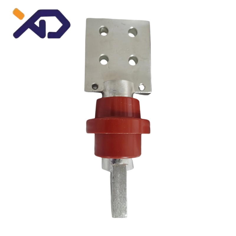
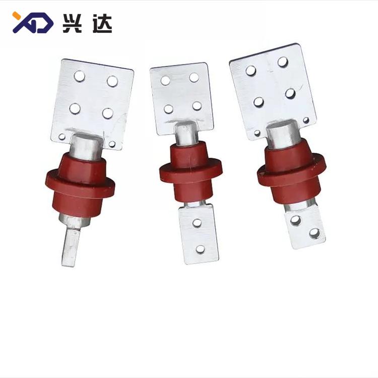
- 1 kV Dry‑Type Epoxy Resin Bushing (1000A‑3150A)Low‑voltage heavy‑current epoxy resin bushing series, designed for 1 kV class transformer equipment. Current grades cover 1000 A, 1600 A, 2000 A and 3150 A. Two terminal angle options are available: 90° and 0° terminal angle to match different busbar layout requirements on‑site. Square‑shaped mounting flange structure fits tank cover opening dimensions for low‑voltage transformer compartments. Mainly used for low‑voltage side outlet of oil‑immersed and dry‑type distribution transformers.
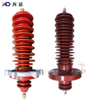
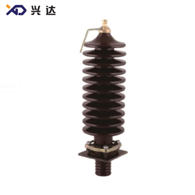
- 35 kV Dry‑Type Epoxy Resin Bushing (315A)Medium‑voltage epoxy resin bushing for 35 kV power transformers, rated current 315 A. Multiple overall height variants are available to satisfy different insulation and creepage requirements. Two mounting flange types: pressure‑plate flange (P) and resin integrated flange (S). Shed quantity and creepage distance are optimized for medium‑voltage outdoor substation conditions. Suitable for 35 kV oil‑immersed power transformers, and can be adapted for moderately polluted outdoor environments.
Core Advantages of Epoxy Resin Bushing
- High Mechanical Strength: Cast epoxy resin structure resists impact, shock and vibration. Compared with fragile porcelain bushings, epoxy resin bushings greatly reduce risk of cracking during transportation, installation and operation.
- Excellent Anti‑Pollution Performance: Molded shed geometry extends creepage distance, suppresses surface flashover risk under dusty, humid and industrial‑polluted atmospheric conditions.
- Compact Structure: Dry‑type solid insulation design, no internal oil filling required. Simplifies overall equipment layout and eliminates oil‑leakage hazards associated with oil‑filled bushing designs.
- Flexible Mounting Options: Multiple flange forms, terminal angles and thread specifications are available. For 1 kV models, 0° / 90° terminal angles adapt to various busbar routing; for 35 kV models, pressure‑plate flange and resin‑integrated flange offer two installation solutions.
- Stable Partial‑Discharge Performance: High‑quality epoxy casting process minimizes internal voids, keeps low partial‑discharge level for long‑term service life.
- Wide Current Coverage: 1 kV series supports heavy‑current output up to 3150 A, meeting high‑capacity distribution transformer low‑voltage terminal demands.
- Customizable Dimensions: Overall height, mounting hole layout and connection sizes can be adjusted to match special transformer tank‑cover opening requirements for retrofit projects.
Good Thermal Stability: Optimized conductor cross‑section restrains hot‑spot temperature rise under continuous rated‑current operation.
Typical Application Scenarios
Technical Specifications
Table 1: 1 kV Dry‑Type Epoxy Resin Bushing (1000A‑3150A)
| Code 代号 | Model 型号 | H | h 2 | h3 | d | d1 | d3 | d4 | B1×B2 | t | B3×B4 | t1 | c1×c2 | d0 箱盖开孔 | creep distance 爬距 | terminal angle 端子角度 | weight (kg) 重量 |
|---|---|---|---|---|---|---|---|---|---|---|---|---|---|---|---|---|---|
| XD.GSTG.02.A | BFG‑1KV/1000A | 267 | 111 | 78 | 30 | 55 | 55 | 26 | 80×80 | 10 | 22×26 | 10 | 80×80 | 57 | 35 | 90° | 2 |
| XD.GSTG.02.B | BFG‑1KV/1000A | 267 | 111 | 78 | 30 | 55 | 55 | 26 | 80×80 | 10 | 22×26 | 10 | 80×80 | 57 | 35 | 0° | 2 |
| XD.GSTG.03.A | BFG‑1KV/1600A | 267 | 111 | 78 | 36 | 70 | 70 | 26 | 80×80 | 12 | 22×26 | 12 | 80×80 | 57 | 35 | 90° | 2.6 |
| XD.GSTG.03.B | BFG‑1KV/1600A | 267 | 111 | 78 | 36 | 70 | 70 | 26 | 80×80 | 12 | 22×26 | 12 | 80×80 | 57 | 35 | 0° | 2.6 |
| XD.GSTG.04.A | BFG‑1KV/2000A | 287 | 111 | 78 | 42 | 70 | 70 | 31 | 100×100 | 12 | 22×26 | 15 | 80×80 | 72 | 40 | 90° | 3.5 |
| XD.GSTG.04.B | BFG‑1KV/2000A | 287 | 111 | 78 | 42 | 70 | 70 | 31 | 100×100 | 12 | 22×26 | 15 | 80×80 | 72 | 40 | 0° | 3.5 |
| XD.GSTG.05.A | BFG‑1KV/3150A | 287 | 111 | 78 | 48 | 70 | 70 | 31 | 100×100 | 16 | 22×26 | 20 | 80×80 | 72 | 40 | 90° | 4.5 |
| XD.GSTG.05.B | BFG‑1KV/3150A | 287 | 111 | 78 | 48 | 70 | 70 | 31 | 100×100 | 16 | 22×26 | 20 | 80×80 | 72 | 40 | 0° | 4.5 |
Notes: Custom dimensions are available on request; overall H height can be adjusted according to project requirements.
Table 2: 35 kV Dry‑Type Epoxy Resin Bushing (315A)
| Sequence Number 序号 | Code 代号 | Model 型号 | H | h2 | h3 | Md | d1 | d2 | d3 | d0 箱盖开孔 | h1 干弧距离 arcing distance | creep distance 爬距 | shield 伞形 | conductive rod mode 导电杆方式 | flange mode 法兰安装方式 | view 视图 | weight (kg) 重 量 |
|---|---|---|---|---|---|---|---|---|---|---|---|---|---|---|---|---|---|
| 1 | XD.GSTG.35.001 | BFGM‑35KV/315A | 580 | 122 | 40 | M12*1.75 | 145 | 180 | 90 | 105 | 365 | 1256 | 8 大 9 小 | W | P | 图 1 | 9.5 |
| 2 | XD.GSTG.35.002 | BFGM‑35KV/315A | 660 | 122 | 40 | M12*1.75 | 145 | 180 | 90 | 105 | 445 | 1530 | 10 大 11 小 | W | P | 图 1 | 10.9 |
| 3 | XD.GSTG.35.003 | BFGM‑35KV/315A | 610 | 140 | 40 | M12*1.75 | 142.5 | 210 | 100 | 105 | 400 | 1440 | 9 大 9 小 | W | S | 图 2 | 11.5 |
| 4 | XD.GSTG.35.004 | BFGM‑35KV/315A | 610 | 130 | 40 | M12*1.75 | 146 | 240 | 100 | 105 | 410 | 1400 | 8 大 8 小 | W | S | 图 3 | 13 |
Notes:
- Mounting mode P = Pressure‑plate flange; S = Resin flange; Conductive rod mode W = External thread.
- All data represents standard industry reference specifications.
Selection Criteria for Epoxy Resin Bushing
- Rated Voltage and Rated Current: Match bushing voltage class and current rating to transformer nominal parameters. For low‑voltage transformer outlets, select 1 kV epoxy resin bushing from 1000 A‑3150 A; for 35 kV transformer terminals, adopt 35 kV / 315 A epoxy resin bushing.
- Terminal Angle (1 kV models): Choose 0° or 90° terminal angle according to physical busbar layout on‑site to avoid installation interference.
- Mounting Flange Type: For 35 kV applications, decide between pressure‑plate flange (P) or resin‑integrated flange (S), verify tank‑cover opening dimension d0 before ordering.
- Creepage and Dry‑arc Distance: Evaluate site pollution grade; pick suitable shed profile and creepage distance for industrial or coastal polluted locations.
- Overall Dimension Constraints: Confirm total height H and surrounding clearance space inside transformer compartment. Custom height modification is supported for special‑purpose units.
- Standard Compliance: Verify products conform to relevant IEC and national power‑equipment standards for transformer bushings.
Installation & Maintenance Guidance
Pre‑installation Inspection
- Visually examine epoxy resin surface. Reject units with cracks, chipping, scratches or tracking damage on casting body and sheds.
- Check all dimensional parameters against drawing requirements: flange hole positions, thread size, terminal dimensions and tank‑cover opening compatibility.
- Confirm factory test reports including power‑frequency withstand voltage, impulse voltage and partial‑discharge test records.
Installation Notes
Routine Maintenance
‑ All maintenance tasks must be completed with transformer fully de‑energized. Do not disassemble epoxy resin bushing internal components in field conditions.
Conclusion
Categories
Contact Us
Contact: Tianjin Delda Trading Co., Ltd
WhatsApp: +86 13662056855
Tel:
E-mail: solomon20210701@tjxddq.com
Add: Unit‑101, Workshop 3, Bozhong Automobile Industrial Park, No.5 Xianghui Road, Intersection of Xianghui Road and Gaoying Road, Beizhakou Town, Jinnan District, Tianjin, China