National Standard Bushing
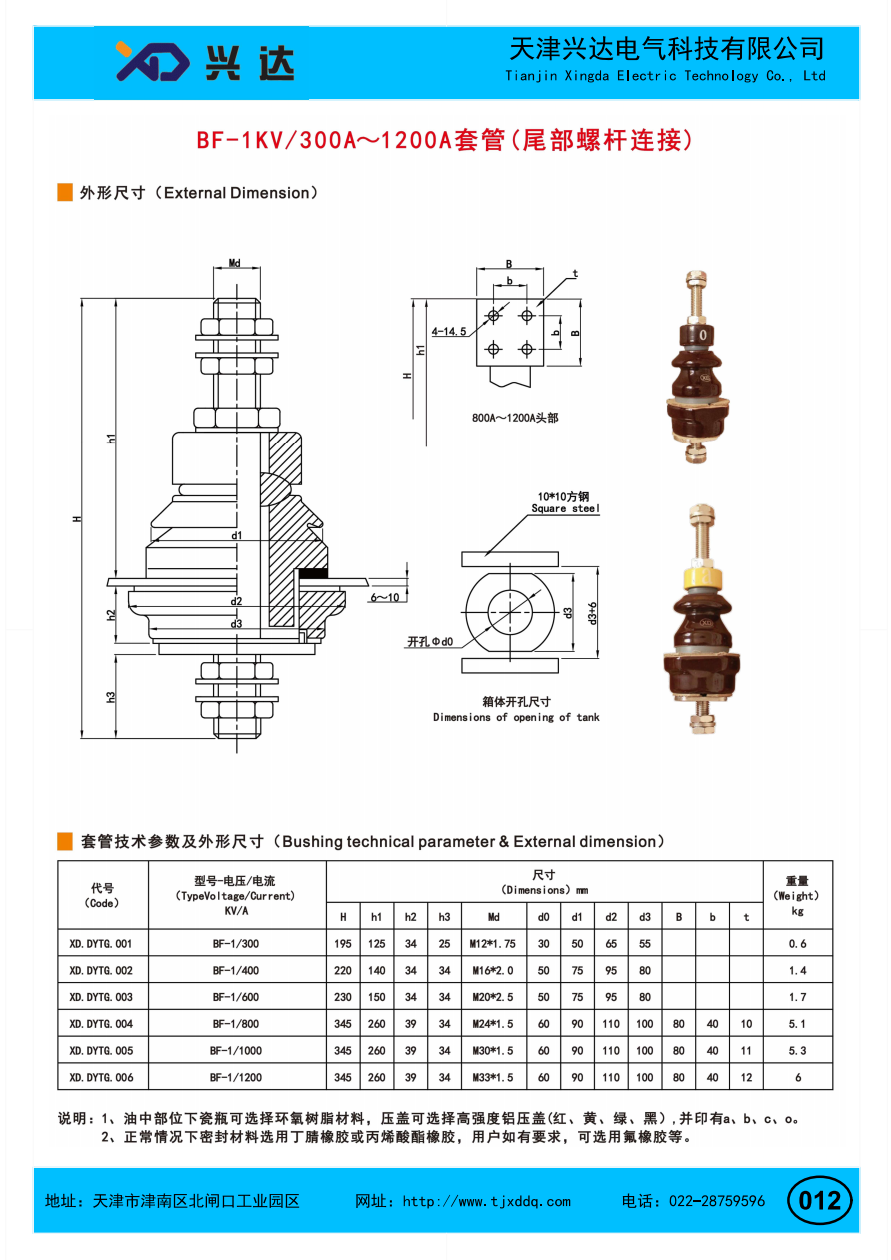
BF-1KV/300A-1200A National Standard Bushing(Rear threaded‑rod connection)
BF‑1KV/300A‑1200A National Standard Bushing (Rear threaded‑rod connection)
Overview
A BF‑1KV/300A‑1200A national standard bushing with rear threaded‑rod connection is a low‑voltage insulating component widely applied for oil‑immersed distribution transformers. This bushing family is designed for rated system voltage of 1 kV, covering continuous current ratings from 300 A up to 1200 A. The rear threaded‑rod connection refers to the threaded stud structure at the bottom tail of the bushing, which provides reliable mechanical fastening and electrical connection for internal transformer winding conductors inside the oil‑filled tank.
As a tank‑mount feed‑through insulator, this bushing allows live conductors to pass safely through the earthed metal transformer tank wall. It delivers two core functions: high‑level electrical insulation between energized parts and the grounded tank, and solid mechanical support for conductive connections both at the top terminal and the rear tail threaded‑rod. Low‑voltage transformer bushings are frequently underestimated; defective or improperly‑specified units can cause partial discharge, overheating at connection joints, oil leakage and unexpected transformer shutdown, even within 1 kV low‑voltage class.
BF‑1KV series bushings follow national standard dimensional and electrical requirements for distribution transformers. They adopt composite or porcelain insulating sheds, multi‑layer sealing structures, and configurable pressure cover materials. The rear threaded‑rod connection is the key mechanical feature of this series. Installed inside transformer oil compartment, the tail threaded stud fastens inner winding leads firmly, avoiding loose contact under load cycling, mechanical vibration and oil temperature variation.
These bushings are extensively used in small‑to‑medium oil‑immersed distribution transformers, industrial auxiliary transformers, and power‑supply transformers for commercial facilities. They support both original equipment manufacturing and field spare‑part replacement work. Sealing rubber components can be selected according to medium compatibility, including nitrile butadiene rubber, acrylate rubber and fluororubber for special‑oil operating conditions.
What is Rear Threaded‑rod Connection for BF‑1KV Bushing
The rear threaded‑rod connection is the bottom tail threaded stud of the bushing assembly. Unlike top external terminals for overhead busbar connection, this threaded rod extends into the transformer oil tank, dedicated for fastening internal winding leads. Different bushing current grades are equipped with different thread specifications ranging from M12×1.75 up to M30×1.5 to match corresponding current‑carrying capacity.
The complete BF‑1KV bushing assembly consists of insulating housing, upper external terminal hardware, flange mounting structure, sealing gaskets, and rear threaded‑rod connection at the bottom. The tank opening dimension is standardized for 1 kV distribution transformer tank mounting. Insulation body can be porcelain or epoxy resin material, and pressure covers are available in multiple colors for phase identification (red, yellow, green, black).
Every BF‑1KV series bushing must pass standard type tests: power‑frequency withstand voltage test, temperature‑rise test under rated current, short‑time withstand current test, mechanical torque test for rear threaded‑rod joint, and oil‑tight sealing test. Good mechanical strength of rear threaded‑rod connection is critical, because loose tail joints will trigger local overheating and accelerate insulation ageing inside transformer oil.
Core Advantages of BF‑1KV/300A‑1200A National Standard Bushing (Rear threaded‑rod connection)
- Reliable rear threaded‑rod connection for internal winding wiringGraded thread sizes match each current rating from 300 A‑1200 A. The rear threaded‑rod connection provides stable bolt‑fastening interface for transformer inner leads. It resists loosening caused by long‑time vibration and thermal cycling during transformer operation, lowering overheating risk at internal connection points.
- Flexible material configuration for diversified working conditionsInsulating housing can adopt porcelain or epoxy resin material. Multi‑color aluminum pressure covers support phase marking. Sealing gaskets offer multiple rubber options including nitrile rubber, acrylate rubber and fluororubber, adapting to different transformer oil types and temperature ranges.
- Broad current coverage for low‑voltage transformer applicationsThis bushing series covers 300 A, 400 A, 600 A, 800 A, 1000 A and 1200 A continuous current under 1 kV rated voltage. It satisfies various low‑voltage side requirements for distribution transformers of different power capacities.
- Optimized sealing performance against transformer oil leakageMulti‑layer gasket sealing structure between bushing flange and transformer tank prevents mineral oil leakage. Standardized tank‑opening dimensions simplify installation and replacement without complex tank modification.
- Balanced mechanical and dielectric performanceSufficient mechanical strength for mounting torque on top terminals and rear tail threaded‑rod. Qualified low‑voltage insulation performance avoids surface flash‑over. Compact overall dimension saves installation space inside transformer tank.
Technical Specification Table: BF‑1KV/300A‑1200A National Standard Bushing (Rear threaded‑rod connection)
| Model | Rated Voltage(kV) | Rated Current(A) | H(mm) | h1(mm) | h2(mm) | h3(mm) | Md Thread | d0(mm) | d1(mm) | d2(mm) | d3(mm) | Weight(kg) |
|---|---|---|---|---|---|---|---|---|---|---|---|---|
| BF‑1/300 | 1 | 300 | 190 | 120 | 34 | 25 | M12×1.75 | 30 | 50 | 65 | 55 | 0.6 |
| BF‑1/400 | 1 | 400 | 220 | 140 | 34 | 34 | M16×2.0 | 50 | 75 | 95 | 80 | 1.4 |
| BF‑1/600 | 1 | 600 | 230 | 150 | 34 | 34 | M20×2.5 | 50 | 75 | 95 | 80 | 1.7 |
| BF‑1/800 | 1 | 800 | 345 | 260 | 39 | 34 | M24×1.5 | 60 | 90 | 110 | 100 | 5.1 |
| BF‑1/1000 | 1 | 1000 | 345 | 260 | 39 | 34 | M30×1.5 | 60 | 90 | 110 | 100 | 5.3 |
| BF‑1/1200 | 1 | 1200 | 345 | 260 | 39 | 34 | M30×1.5 | 60 | 90 | 110 | 100 | 6.0 |
Note: All dimensions are in millimeters. Custom dimensions are acceptable upon request. Pressure‑cover color and sealing rubber material can be selected according to project requirements.
Typical Application Scenarios
‑ Oil‑immersed national‑standard distribution transformers, low‑voltage side bushing ‑ Industrial plant auxiliary oil‑filled transformers ‑ Commercial building power‑supply transformers ‑ Transformer maintenance, retrofit and spare‑part replacement projects ‑ Special‑purpose transformers requiring fluororubber sealing for special insulating oil
The rear threaded‑rod connection sits inside transformer oil, connecting to winding lead terminals directly. Engineers shall select proper thread specification, current rating and sealing material according to transformer nameplate data, oil medium and operating temperature range.
Key Selection Criteria
- Current and voltage rating: Confirm 1 kV rated voltage and continuous operating current (300A‑1200A) matching transformer low‑voltage side parameter.
- Rear threaded‑rod thread size: Thread specification Md increases with current rating, ensure compatibility with transformer winding lead connection hardware.
- Sealing material selection: Nitrile rubber for conventional mineral transformer oil; choose fluororubber for special oil or high‑temperature working conditions.
- Insulator & pressure‑cover option: Choose porcelain or epoxy resin insulation; select pressure‑cover color for phase identification when required.
- Mechanical dimension: Verify tank opening size, mounting space, overall H dimension to avoid interference inside transformer tank.
Installation Guidance
‑ Inspect insulation body for cracks, gasket integrity and rear threaded‑rod surface damage before assembly. Damaged threads will cause poor inner contact. ‑ Install sealing gasket between bushing flange and transformer tank wall; evenly fasten mounting bolts with recommended torque value, avoid over‑tightening to prevent insulator cracking. ‑ Connect transformer internal winding leads onto rear threaded‑rod connection inside oil tank, apply correct torque for inner fastening nuts. Do not apply excessive bending force on tail threaded stud. ‑ Complete top‑terminal wiring outside tank. Install phase‑color pressure‑cover as required. ‑ Carry out oil‑leakage inspection after installation, and perform relevant dielectric tests before transformer energization.
Routine Maintenance Guidance
‑ During transformer overhaul, visually inspect insulator surface for contamination or cracks. ‑ Check rear threaded‑rod joint condition when transformer tank is opened; inspect for thread corrosion, loose nuts and signs of local overheating. ‑ Replace ageing sealing gaskets during maintenance to prevent future oil leakage. ‑ Check pressure‑cover status; replace damaged or faded phase‑identification covers. ‑ If insulation cracking or thread deformation is detected, replace the whole bushing assembly immediately.
Conclusion
BF‑1KV/300A‑1200A national standard bushing with rear threaded‑rod connection is a mature low‑voltage feed‑through insulating component for oil‑immersed distribution transformers. Its defining rear threaded‑rod tail structure provides stable internal connection for winding leads inside transformer oil tank. Flexible choices over insulator material, sealing rubber and multi‑color pressure‑covers enable adaptation for multiple transformer‑manufacturing and maintenance scenarios.
Reasonable model selection, torque‑controlled standardized installation and regular overhaul inspection help prevent oil leakage and internal joint over‑heating faults, supporting long‑term safe and stable operation of low‑voltage sides for national‑standard oil‑immersed transformers.
Categories
Contact Us
Contact: Tianjin Delda Trading Co., Ltd
WhatsApp: +86 13662056855
Tel:
E-mail: solomon20210701@tjxddq.com
Add: Unit‑101, Workshop 3, Bozhong Automobile Industrial Park, No.5 Xianghui Road, Intersection of Xianghui Road and Gaoying Road, Beizhakou Town, Jinnan District, Tianjin, China