EN Bushing
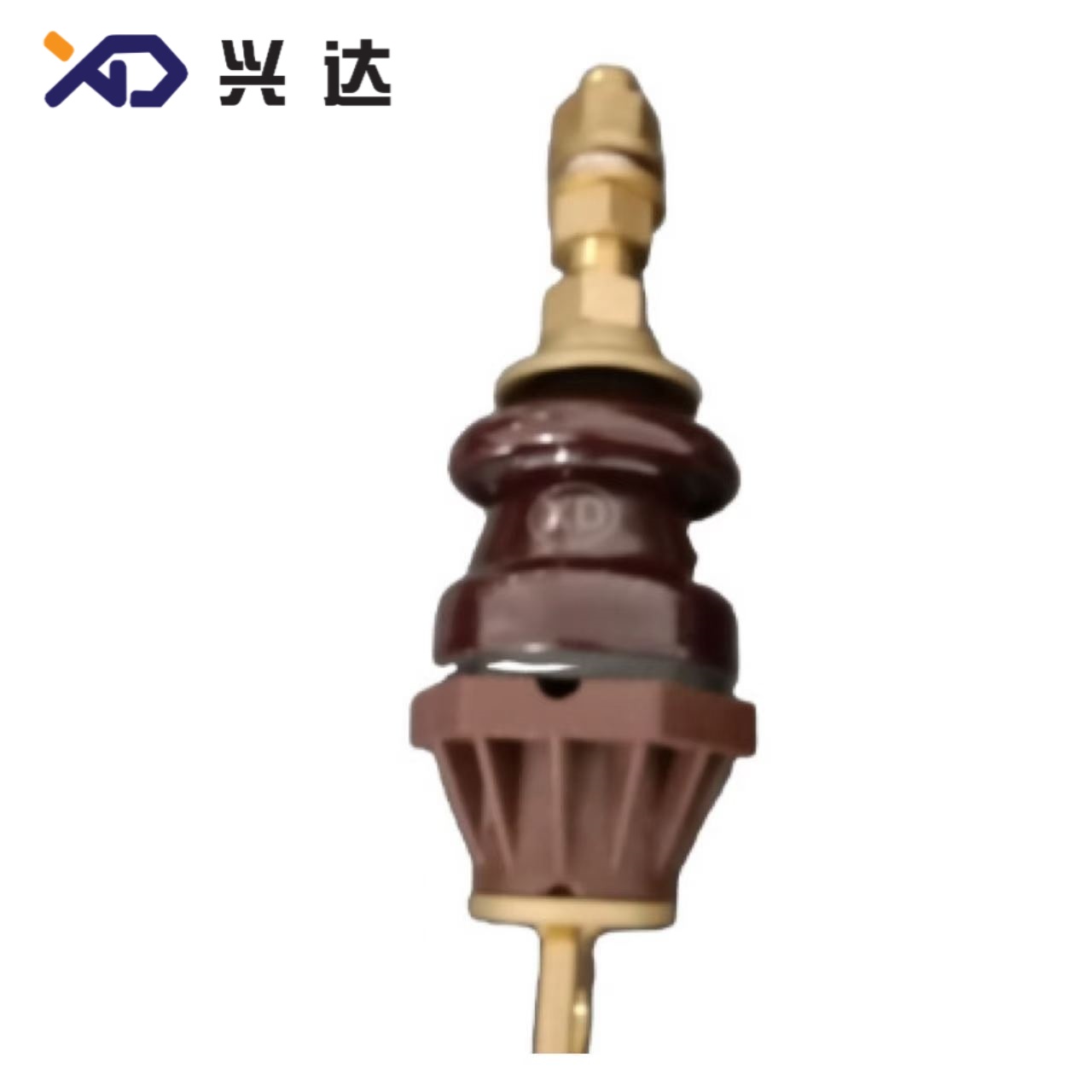
EN Transformer Bushing: Complete Technical Guide for 1‑3 kV Oil‑Immersed Transformers
EN Transformer Bushing: Complete Technical Guide for 1‑3 kV Oil‑Immersed Transformers
(Font: Times New Roman)
Overview of EN Transformer Bushing
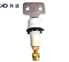
An EN transformer bushing is a standardized insulating through‑fitting built to European Norm specifications, widely deployed on oil‑immersed distribution transformers for rated voltages of 1 kV to 3 kV and rated currents ranging from 250 A up to 3150 A天津兴达电.... This bushing assembly creates a safe insulated passage for live current‑carrying conductors passing through the earthed metal tank cover of liquid‑filled transformers. Without this critical component, energized internal winding leads cannot exit the transformer tank without risk of surface flash‑over, leakage current, or phase‑to‑ground short‑circuit faultsIEEE Techn....
EN‑series bushings follow dimensional, mechanical, dielectric and creepage‑distance rules defined under European standards EN 50386 and related product norms for liquid‑filled transformer accessories. The term “EN bushing” is a high‑frequency search keyword among transformer OEM engineers, EPC contractors, maintenance technicians, and electrical procurement teams across European, Middle‑Eastern and global distribution‑power markets. Related search variants include EN porcelain bushing, EN low‑voltage transformer bushing, EN tank‑cover bushing, EN‑compliant transformer through insulator, and EN flag‑type bushing terminals天津兴达电....
Typical construction for standard EN bushing units includes a solid porcelain insulating housing, brass or copper central conductive stud / flag terminal assembly, compression metal fittings, and oil‑resistant elastomer sealing gaskets. One side of the insulator sits inside transformer mineral oil, while the opposite end operates in open atmospheric air. This mixed‑medium operating condition imposes strict requirements for sealing performance, thermal cycling resistance, surface creepage performance, and mechanical cantilever load capacity.
Core Functions of EN‑Standard Bushing
- Current Conduction: Deliver continuous rated load current from internal transformer windings out to external bus‑bar or cable connections, maintaining low contact resistance to avoid thermal over‑heating at connection points.
- Galvanic Insulation: Isolate high‑potential live conductors completely from the grounded transformer tank wall, preventing earth‑fault discharge.
- Mechanical Mounting Support: Act as a rigid mounting anchor to withstand static weight of external connections plus dynamic short‑circuit mechanical forces, vibration from transformer operation, and minor seismic loads.
- Oil‑Tight Environmental Sealing: Preserve transformer tank integrity; stop mineral‑oil leakage outwards and block moisture, dust and atmospheric contaminants from penetrating into the transformer oil compartment.
- Controlled Surface Creepage Performance: Provide defined creepage distance along the external insulator surface to suppress leakage current and outdoor pollution‑caused flash‑over events under humid, foggy or contaminated ambient operating conditions.
Key Advantages of EN‑Series Transformer Bushings
- Fully Standardized Interchangeable Dimensions: Mounting hole diameters, thread specifications, overall heights and flange dimensions are standardized according EN norms. This allows drop‑in replacement between different qualified manufacturers without tank cover re‑machining, greatly simplifying transformer after‑sales maintenance and spare‑part inventory management.
- Broad Rated‑Current Coverage: Product portfolio covers low‑current 250 A distribution‑transformer ratings through heavy‑duty 3150 A units for larger power‑distribution transformers.
- Proven Porcelain Insulator Reliability: Porcelain‑housed EN bushings deliver stable dielectric performance, strong resistance against thermal ageing, ozone degradation and UV exposure for long service‑life in both indoor and outdoor installations.
- Optimized Creepage‑Distance Options: Multiple creepage‑distance grades are available to match different pollution‑level site classifications, covering general‑purpose rural locations as well as moderately polluted industrial environments.
- Robust Sealing Structure: Multi‑layer gasket arrangements handle repeated thermal expansion and contraction cycles caused by transformer load fluctuations, minimizing risk of slow oil seepage over decades of field operation.
- Wide Compatibility: Designed for retrofitting or original equipment fitment for most European‑pattern oil‑immersed distribution transformers working at 1 kV to 3 kV nominal system voltage天津兴达电....
Primary Application Scenarios for EN Transformer Bushings
- New‑build oil‑immersed distribution transformers (1‑3 kV class) for residential and commercial power‑supply networks
- Transformer repair, overhaul and spare‑part replacement projects
- Renewable‑energy step‑down transformers for solar and wind farm auxiliary power circuits
- Industrial‑plant in‑house distribution transformers
- Compact substation transformer units, package‑type distribution substations
- Export‑oriented transformer OEM projects targeting markets adopting European electrical component standards
Important note: EN‑1 / EN‑3 designation differentiates voltage‑class variants within this product family. EN‑1 corresponds to 1 kV rated working voltage, while EN‑3 corresponds to 3 kV rated working voltage. End‑users must strictly match bushing voltage rating with actual transformer low‑side system voltage during part selection.
Technical Specifications & Dimension Tables
All dimension values in the following tables are given in millimetres (mm). Creepage distance values represent external air‑side surface creepage length.
Table 1: EN Transformer Bushing Dimensions – 250 A ~ 630 A Range
表格
| Serial number | Code | Model | H | h2 | h3 | t | Md Thread | d1 | d2 | S | S1 | Tank‑cover opening d0 | Creep distance |
|---|---|---|---|---|---|---|---|---|---|---|---|---|---|
| 1 | XD.0250.1.EN | EN‑1/250 | 187 | 30 | 3‑6 | 5 | M12*1.75 | 53 | 11 | 22 | 15 | 26 | 55 |
| 2 | XD.0250.3.EN | EN‑3/250 | 213 | 35.5 | 36 | 5 | M12*1.75 | 60 | 6.5 | 22 | 15 | 45 | 95 |
| 3 | XD.0630.1.EN | EN‑1/630 | 235 | 30 | 3‑6 | 9 | M20*2.5 | 70 | 12 | 32 | 14 | 45 | 70 |
Where:
- H: Overall total height of bushing assembly
- h2: Height dimension from mounting flange down to internal oil‑side end
- h3: Internal insertion depth tolerance range
- t: Thickness of transformer tank‑cover mounting plate compatible range
- Md: Main conductive stud thread specification
- d1: Outer diameter of upper porcelain insulator
- d2: Diameter of internal conductive part
- S, S1: Spacing dimensions for internal fastening hardware
- d0: Required tank‑cover cut‑out hole diameter
- Creep distance: External insulator creepage path length (mm)
Table 2: EN Transformer Bushing Dimensions – 1000 A ~ 3150 A Heavy‑Current Range
High‑current EN‑series bushings (1000 A up to 3150 A) adopt flag‑type multi‑hole flat terminal connections instead of simple single‑stud terminals. The A‑view mounting terminal plate features either two‑hole layout (for 1000 A‑1250 A grades) or four‑hole layout (for 2000 A‑3150 A grades).
表格
| Serial number | Code | Model | H | h2 | h3 | t | Md Thread | d1 | d2 | S | S1 | a2×a2 | a1×a1 | d4 | Tank‑cover opening d0 | Creep distance |
|---|---|---|---|---|---|---|---|---|---|---|---|---|---|---|---|---|
| 1 | XD.1000.1.EN | EN‑1/1000 | 268 | 39 | 3‑6 | 12 | M30*2.0 | 90 | 2×6.7 | 57 | 15 | 60×60 | 26×26 | 14 | 56 | 75 |
| 2 | XD.1250.1.EN | EN‑1/1250 | 268 | 39 | 36 | 12 | M30*2.0 | 90 | 2×6.7 | 57 | 15 | 60×60 | 26×26 | 14 | 56 | 75 |
| 3 | XD.2000.1.EN | EN‑1/2000 | 314 | 45 | 6‑10 | 15 | M42*3.0 | 104 | 2×13 | 10 | 15 | 100×100 | 50×50 | 14 | 70 | 75 |
| 4 | XD.3150.1.EN | EN‑1/3150 | 318 | 45 | 6‑10 | 15 | M48*3.0 | 125 | 3×13 | 10 | 15 | 120×120 | 60×60 | 14 | 90 | 75 |
Additional definitions for high‑current table fields:
- a2×a2: Outer overall dimension of flag‑type terminal plate
- a1×a1: Centre‑to‑centre hole pitch dimension of terminal mounting holes
- d4: Diameter of terminal plate bolt holes
Critical Selection Criteria for EN‑Type Transformer Bushings
When specifying or replacing an EN transformer bushing, design and procurement engineers must evaluate these parameters to avoid compatibility or reliability risks:
- Rated Voltage Matching: Confirm nominal transformer low‑side voltage (1 kV or 3 kV). Mixing EN‑1 and EN‑3 types will create insufficient insulation margin or incorrect creepage performance.
- Rated Current Rating: Select bushing rated current greater‑than or equal to maximum continuous operating current of the transformer winding. For overload‑capable transformers, consider applying a safety margin of 10‑15 % above nominal winding current.
- Tank‑cover Opening Size: Verify tank‑cover hole diameter
d0. The opening must match bushing specification; oversized openings break sealing compression; undersized holes prevent physical installation. - Tank‑plate Thickness “t”: The mounting plate thickness of transformer tank cover must sit within the “t” tolerance range given in specification tables to guarantee proper gasket compression for oil‑tight sealing.
- Creepage Distance Requirement: Choose adequate creepage distance corresponding to site pollution class. Industrial, coastal or salt‑fog environments require extended creepage‑distance variants to suppress pollution flash‑over events.
- Terminal Connection Style: Distinguish single‑stud low‑current terminals versus multi‑hole flag‑type flat terminals for high‑current models (1000 A‑3150 A). Terminal hole pattern must align with customer bus‑bar or cable lug geometry.
- Mechanical Cantilever Load: Check permitted lateral cantilever load for bushing terminals. External bus‑bar weight and short‑circuit dynamic forces must not exceed the mechanical strength limits defined in EN 50386 test standards, to avoid porcelain cracking or seal damage.
Installation & Operational Best Practices
- Inspect porcelain insulator surface before installation for chips, cracks or glaze damage. Damaged porcelain must never be fitted into service, as cracks allow oil leakage and accelerate dielectric failure.
- Apply uniform torque to fastening nuts. Over‑torque will crack porcelain housing; insufficient torque leads to oil seepage and loose contact heating.
- Replace all rubber sealing gaskets during bushing replacement work; re‑using aged gaskets is a very common source of slow transformer oil‑leakage faults.
- After installation, perform visual inspection for oil leakage. Carry‑out routine periodic visual checks during transformer maintenance cycles, especially for units located in polluted outdoor environments.
- For outdoor‑sited transformers, regular cleaning of porcelain external surfaces reduces surface leakage current risk in heavy‑dust or salt‑spray locations.
- Avoid applying excessive mechanical side‑force onto bushing terminals when connecting bus‑bars or cable lugs; flexible connector links can absorb thermal‑expansion displacement and reduce static mechanical stress transferred to the bushing assembly.
Common Failure Modes for EN‑Series Bushings in Field Service
- Oil leakage: Most often caused by worn gaskets, uneven tightening torque, or tank‑plate thickness outside the “t” design range.
- Terminal overheating: Arises from insufficient contact pressure, corroded terminal surfaces, or selecting a bushing with insufficient rated‑current capacity.
- Porcelain fracture: Induced by excessive cantilever side‑load, mechanical impact during transport or installation, or thermal‑shock stress.
- Outdoor surface flash‑over: Triggered when creepage distance is inadequate for site pollution levels, combined with wet or foggy weather conditions.
- Internal insulation degradation: Occurs if moisture penetrates through defective seals, contaminating the boundary zone between porcelain insulator and transformer mineral oil.
Summary
EN transformer bushings form an indispensable interface component for European‑standard oil‑immersed distribution transformers operating in the 1 kV‑3 kV voltage class, covering continuous‑current ratings spanning from 250 A up to 3150 A. Their standardized dimensional layout supports interchangeable replacement, reducing transformer manufacturing cost and field‑maintenance complexity. Successful application depends on careful matching of rated voltage, rated current, tank‑opening dimensions, mounting‑plate thickness, creepage‑distance for site pollution grade, and terminal connection geometry. Adherence to proper installation torque, gasket renewal practice, and periodic visual inspection greatly extends service life and minimises transformer unplanned outages caused by bushing‑related faults.
Categories
Contact Us
Contact: Tianjin Delda Trading Co., Ltd
WhatsApp: +86 13662056855
Tel:
E-mail: solomon20210701@tjxddq.com
Add: Unit‑101, Workshop 3, Bozhong Automobile Industrial Park, No.5 Xianghui Road, Intersection of Xianghui Road and Gaoying Road, Beizhakou Town, Jinnan District, Tianjin, China