DIN Bushing
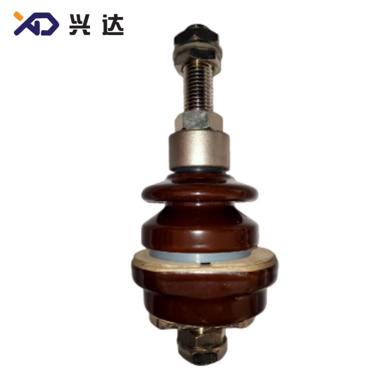
DIN Bushing: Complete Technical Guide for Oil‑Immersed Distribution Transformers and Medium‑Voltage Power Systems
DIN Bushing: Complete Technical Guide for Oil‑Immersed Distribution Transformers and Medium‑Voltage Power Systems
1. Definition of DIN Bushing
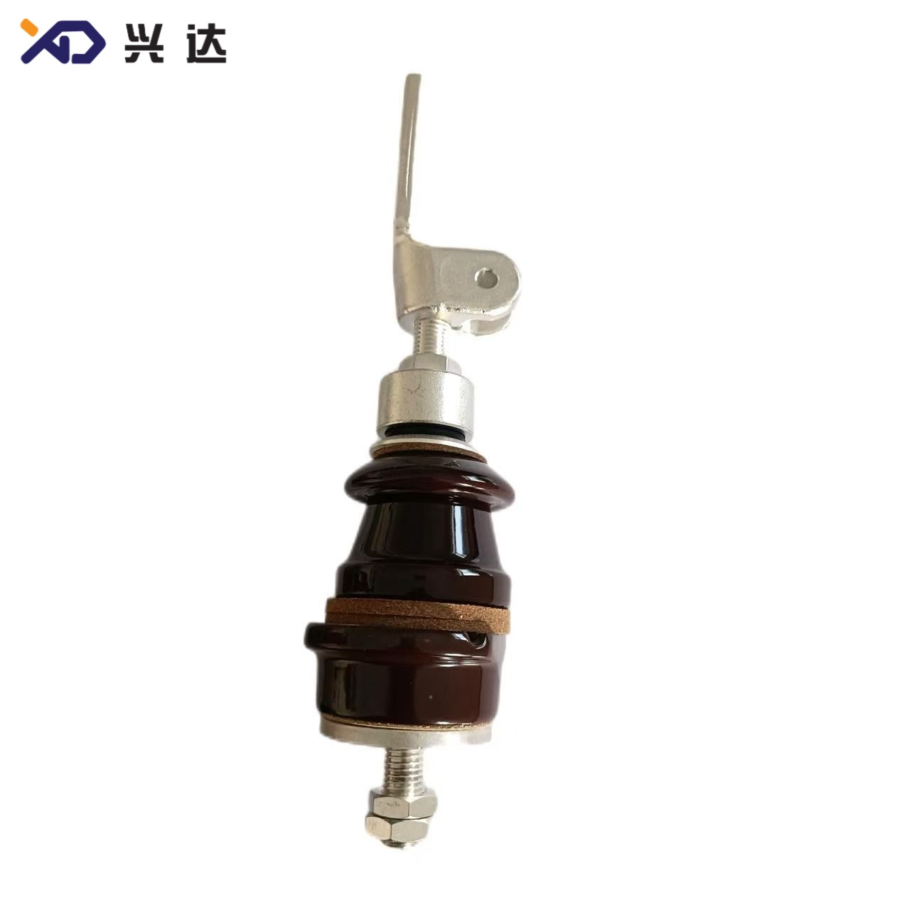
DIN bushing is a medium‑voltage penetration insulating component manufactured following German DIN industrial standards, primarily deployed on oil‑filled distribution transformers, power transformers and associated electrical equipment throughout Europe, the Middle East, Africa and multiple Asian markets. As a critical through‑wall assembly, it enables live high‑current conductors to pass through the earthed metallic transformer tank while maintaining robust electrical insulation between energized copper conductors and the grounded metal housing. Primary governing technical specifications include DIN 42530, DIN 42531, DIN 42532, DIN 42533 and DIN 42534, harmonized alongside EN 50180 and IEC 60137 international bushing standards for equipment operating above 1 kV rated voltage.
Unlike custom‑built non‑standard transformer bushings, DIN‑compliant bushing defines unified metric dimensions for tank cut‑out opening, mounting flange bolt circle, conductor thread specification, shed geometry, minimum creepage distance and dry arcing distance. This strict standardization delivers cross‑manufacturer mechanical interchangeability. Electrical contractors, transformer OEMs and field maintenance teams regularly select DIN bushing for new‑build transformer projects, retrofit upgrades and emergency spare‑part replacement work. Two major material families dominate global installations: high‑alumina porcelain DIN bushing for outdoor harsh‑environment service and cast epoxy resin DIN bushing for indoor switchgear and moderate‑pollution locations.
2. Structure and Operating Principle of DIN Transformer Bushing
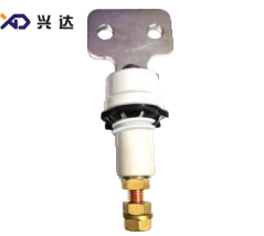
A complete DIN bushing assembly includes five core functional sub‑components: central current‑carrying conductor, main insulating body, metal mounting flange, elastomer sealing gaskets, and external connection terminals. The central conductor is typically constructed from tinned copper or brass to transfer continuous load current and survive short‑circuit fault current during grid disturbance events. The insulator body separates high‑potential live conductor from the grounded transformer tank. Outer shed profiles are engineered to guarantee specified creepage distance to resist surface flash‑over under humid, dusty or salt‑spray coastal operating conditions.
For oil‑immersed transformer DIN bushing, one segment of the insulator sits submerged inside transformer mineral oil, while the shed‑fitted outer section operates in open atmospheric air. Rubber or silicone gaskets fitted between flange surface and transformer tank wall stop transformer oil leakage and prevent atmospheric moisture and dust from entering the transformer tank interior. Modern qualified DIN bushing must maintain partial discharge magnitude below 10 pC at 1.5 times nominal operating voltage; low partial‑discharge performance is essential to achieve multi‑decade service life under continuous grid operation. Standard mounting clearance gap between flange and tank wall falls between 4 mm and 8 mm for proper gasket compression.
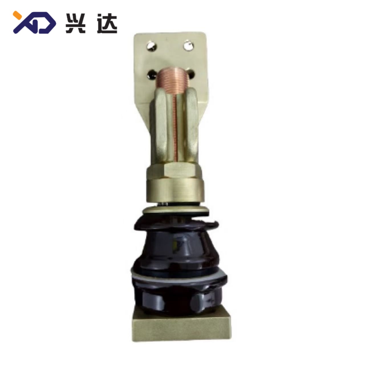
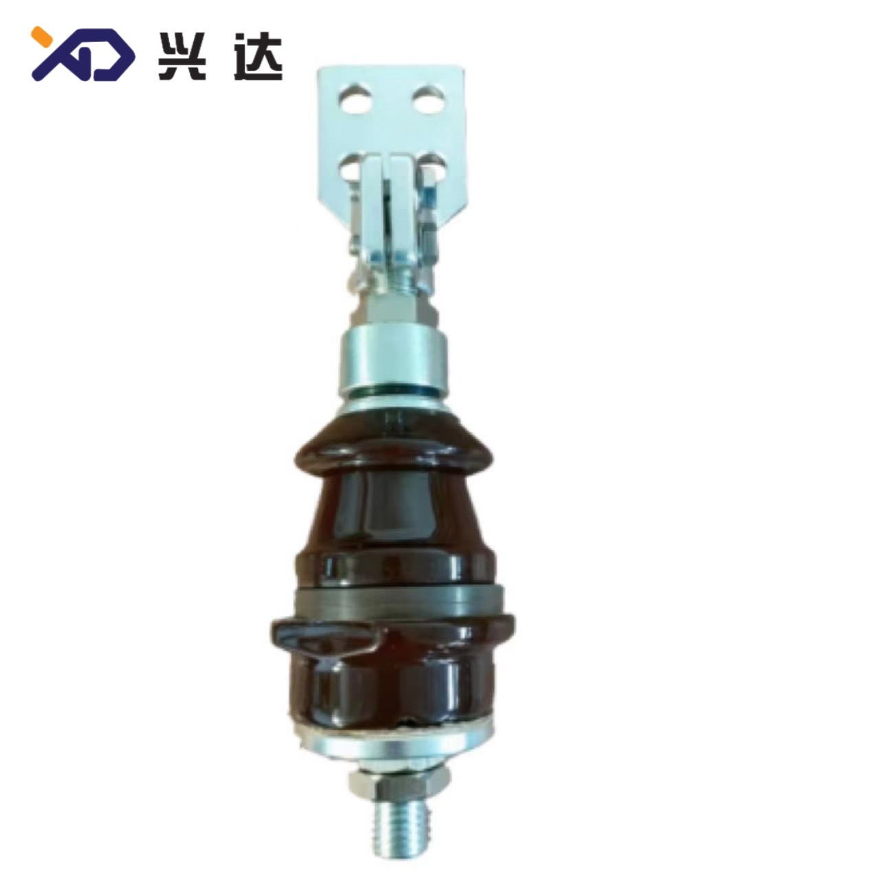
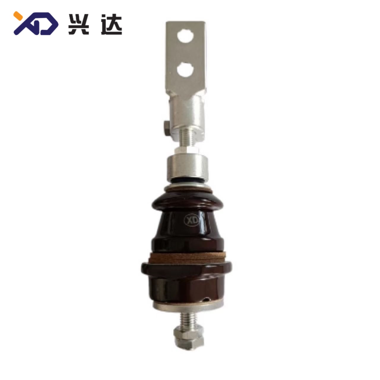
Three primary mechanical configurations exist within the DIN bushing product range. Threaded‑rod DIN bushing uses exposed threaded copper studs for direct bus‑bar connection and is widely used for low‑voltage and medium‑voltage small‑current transformers. Draw‑lead or cable‑through DIN bushing is designed for internal winding cable routing inside transformer tanks, removing external exposed studs and optimizing internal wiring layout. High‑current flat‑plate DIN bushing comes with integrated copper terminal plates, engineered to handle large‑magnitude rated current while limiting temperature rise at connection joints. Each configuration strictly follows DIN dimensional rules to guarantee tank‑mount interchangeability.
3. Key Engineering Advantages of DIN‑Standard Bushing
- Full mechanical interchangeability: Tank opening diameter, flange bolt layout, thread specifications and mounting height comply with unified DIN specifications. DIN bushing units from different manufacturers can replace one‑another without cutting, welding or modifying the transformer tank housing, significantly reducing on‑site labour cost and equipment outage time during transformer maintenance.
- Standardized sealing interface: Flange groove geometry for O‑rings and flat gaskets is standardized, greatly lowering oil‑leakage risk, one of the most frequent failure modes observed for non‑standard transformer through‑wall bushings in field‑service records.
- Wide environmental operating range: Standard‑grade DIN bushing supports ambient temperature ranging from ‑40 °C to +120 °C, making it suitable for cold high‑latitude zones and hot desert project sites. When installed at altitudes higher than 1000 meters above sea‑level, engineers should select bushing with increased creepage distance to compensate reduced air dielectric strength at high elevation.
- Clearly‑defined pollution‑resistance grades: Minimum creepage distance per kilovolt is documented in DIN standard documents, enabling straightforward product selection for heavy‑pollution industrial zones, chemical plant surroundings and marine salt‑fog coastal environments.
- Global certification compatibility: DIN bushing design meets CE marking prerequisites for European Union market access, streamlining conformity assessment for export‑oriented transformer manufacturers.
- Long‑term operational lifespan: Properly installed porcelain DIN bushing can deliver a 25‑30‑year service cycle with regular transformer inspection and maintenance. Epoxy DIN bushing also achieves extended operational life when protected from mechanical impact and intense ultraviolet exposure.
- Multiple connection configurations: The DIN bushing product family covers threaded‑rod connection type, cable‑through draw‑lead style and flat‑plate high‑current terminal variants to match different transformer winding‑outlet mechanical layouts.
4. Main Material Categories of DIN Bushing
Porcelain (Ceramic) DIN Bushing: This is the most widely‑used outdoor variant. High‑alumina porcelain delivers excellent dielectric strength, strong ultraviolet ageing resistance and stable electrical performance across broad temperature fluctuations. Porcelain DIN bushing is extensively used for distribution transformers fitted on outdoor substations, pole‑mounted transformer stations and industrial power‑house locations. Primary disadvantages include comparatively high unit weight and susceptibility to invisible internal cracks caused by sharp mechanical impact. Periodic visual inspection is recommended for porcelain bushings operating in areas with heavy vibration or mechanical hazards.
Cast Epoxy Resin DIN Bushing: Epoxy DIN bushing uses solid cast epoxy polymer as its insulating medium. It features compact outer dimensions, light weight and good anti‑tracking performance for indoor installation scenarios. Epoxy DIN bushing is commonly fitted inside metal‑clad switchgear and enclosed transformer rooms. For permanent open‑air outdoor service without UV shielding, epoxy material will undergo gradual surface degradation; porcelain or silicone‑composite DIN bushing remains the preferred choice for continuous outdoor exposure. Epoxy‑based DIN bushings also show better resistance against minor mechanical knocks compared to brittle porcelain insulators.
Silicone Composite DIN Bushing: As a newer market alternative, silicone composite DIN bushing combines silicone rubber sheds with internal fibre‑reinforced core structures. It brings advantages of lightweight, superior anti‑pollution performance and high resistance to mechanical breakage. Silicone composite DIN bushing gains growing adoption in coastal, heavily contaminated industrial sites, though overall industry stock and spare‑part availability are lower than traditional porcelain DIN bushing.
5. Typical DIN Bushing Application Scenarios
DIN‑standard transformer bushings serve as standard accessories for oil‑immersed distribution transformers within medium‑voltage power grids. Common use‑cases include pole‑mounted distribution transformers, box‑type compact substations, industrial‑plant auxiliary transformers, renewable‑energy step‑up transformers for solar and wind‑farm facilities, and mobile emergency power‑supply transformer units. The DIN bushing product portfolio covers a broad electrical rating scope: rated voltage ranges from 1 kV up to 52 kV; rated current spans from 250 A small‑capacity transformer version to 4500 A heavy‑current bushing for large‑size power transformers.
For transformer retrofitting projects, DIN bushing is the primary option when replacing aged original equipment components. Since dimensions follow unified standards, tank hole modification is rarely required. Project engineers only need to match rated voltage, rated current, creepage requirement and connection style. In export‑oriented transformer manufacturing targeting EU, MEA and CIS markets, DIN‑compliant bushings are frequently specified within tender documents to satisfy local grid authority requirements.
6. DIN Bushing Key Technical Parameters & Dimension Specification Tables
The tables below list representative conventional dimensions for mainstream DIN bushing series, derived from standard industry technical documentation. These values reflect general‑purpose standard sizes; custom dimensional adjustments are available for special project requirements. Key symbol explanation: H = overall total height; h3 = oil‑side lower assembly height; d0 = transformer tank opening diameter; Md = conductor thread specification; Arcing distance = dry arcing clearance; Creepage distance = surface leakage path length; Shed type = insulator shed configuration.
Table 1: 1‑3 kV DIN Bushing (250‑630 A, Threaded‑rod Type)
表格
| Model Reference | Rated Voltage(kV) | Rated Current(A) | Overall Height H(mm) | h3(mm) | Thread Md | Tank Opening d0(mm) | Arcing Distance(mm) | Shed Type |
|---|---|---|---|---|---|---|---|---|
| DIN‑1/250 | 1‑3 | 250 | 260 | 78 | M16×2.0 | 62 | 70 | Single‑shed |
| DIN‑1/630 | 1‑3 | 630 | 272 | 103 | M20×2.5 | 75 | 89 | Single‑shed |
Note: Standard gasket compression clearance between flange and transformer tank wall: 4‑8 mm.
Table 2: 1‑3 kV High‑Current DIN Bushing (1000‑4500 A, Flat‑plate Terminal)
表格
| Model Reference | Rated Voltage(kV) | Rated Current(A) | Overall Height H(mm) | Thread Md | Tank Opening d0(mm) | Terminal Plate Dimension | Arcing Distance(mm) |
|---|---|---|---|---|---|---|---|
| DIN‑1/1000 | 1‑3 | 1000 | 460 | M30×2 | 78 | 60×40 mm | 119 |
| DIN‑1/2000 | 1‑3 | 2000 | 460 | M42×3 | 92 | 60×60 mm | 120 |
Table 3: 12‑36 kV DIN Cable‑through Draw‑lead Bushing (250‑630 A)
表格
| Model Reference | Rated Voltage(kV) | Rated Current(A) | Overall Height H(mm) | h3(mm) | Tank Opening d0(mm) | Creepage Distance(mm) | Arcing Distance(mm) | Shed Quantity |
|---|---|---|---|---|---|---|---|---|
| DIN‑12/250‑630 | 12 | 630 | 559 | 254 | 78 | 310 | 175 | 4‑shed |
| DIN‑24/250‑630 | 24 | 630 | 618 | 344 | 92 | 440 | 355 | 6‑shed |
| DIN‑36/250‑630 | 36 | 630 | 618 | 469 | 92 | 670 | 382 | 9‑shed |
Table 4: 12‑52 kV High‑Current DIN Transformer Bushing (1000‑3150 A)
表格
| Model Reference | Rated Voltage(kV) | Rated Current(A) | Overall Height H(mm) | Thread Md | Tank Opening d0(mm) | Creepage Distance(mm) | Arcing Distance(mm) |
|---|---|---|---|---|---|---|---|
| DIN‑12/2000 | 12 | 2000 | 772 | M48×3.0 | 115 | 350 | 241 |
| DIN‑24/1000 | 24 | 1000 | 722 | M30×2.0 | 115 | 500 | 241 |
| DIN‑24/2000 | 24 | 2000 | 772 | M48×3.0 | 135 | 600 | 300 |
| DIN‑36/3150 | 36 | 3150 | 880 | M48×3.0 | 135 | 750 | 380 |
| DIN‑52/3150 | 52 | 3150 | 1112 | M48×3.0 | 180 | 950 | 480 |
Note: All tabulated dimensions represent standard series values. Custom‑modified dimensions can be implemented for special transformer mechanical layouts.
7. Critical Selection & Installation Guidelines for DIN Bushing
When specifying DIN bushing for a project, engineers must evaluate several key parameters beyond basic voltage and current ratings. First, confirm tank opening diameter, flange bolt‑hole pattern and mounting height to ensure physical fit with transformer tank. Second, calculate required creepage distance based on site pollution class; higher pollution levels require longer creepage path. Third, choose the correct connection style: threaded‑rod, draw‑lead cable‑through or flat‑plate high‑current terminal. Fourth, take altitude correction into account for sites located over 1000 m above sea‑level. Fifth, select insulation material based on indoor or outdoor operating environment, UV exposure and mechanical risk.
During installation, uniform torque must be applied across flange mounting bolts. Uneven bolt torque is a top cause of oil leakage and gasket damage. Never over‑torque porcelain‑type DIN bushing; excessive mechanical stress can create invisible cracks inside the ceramic insulator. Gasket surfaces must be kept clean, free of metal chips, grit or debris before assembly. After installation, perform partial discharge test and power‑frequency withstand test where practical to verify insulation integrity. In‑service maintenance should include periodic visual inspection for oil seepage, surface contamination, shed cracking and connection‑point overheating signs.
8. Common DIN Bushing Failure Modes
Field‑observed typical failures for DIN bushing include oil leakage caused by damaged gaskets or uneven bolt torque, surface flash‑over triggered by insufficient creepage distance under polluted atmosphere, partial‑discharge deterioration from internal insulation defects, mechanical crack damage due to transportation mishandling or over‑torquing, and connection terminal overheating from loose bolted joints. Proper product selection, controlled installation torque and routine visual maintenance can prevent most of these common failure events.
Categories
Contact Us
Contact: Tianjin Delda Trading Co., Ltd
WhatsApp: +86 13662056855
Tel:
E-mail: solomon20210701@tjxddq.com
Add: Unit‑101, Workshop 3, Bozhong Automobile Industrial Park, No.5 Xianghui Road, Intersection of Xianghui Road and Gaoying Road, Beizhakou Town, Jinnan District, Tianjin, China