DIN Bushing
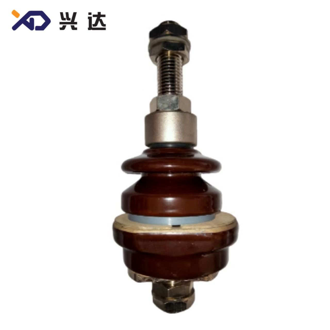
DIN Transformer Bushing – Definition, Working Principle & Primary Application Scenarios
DIN Transformer Bushing – Definition, Working Principle & Primary Application Scenarios
(Font: Times New Roman)
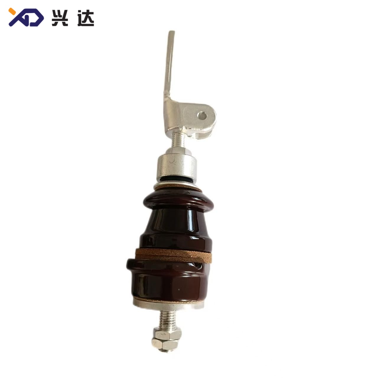
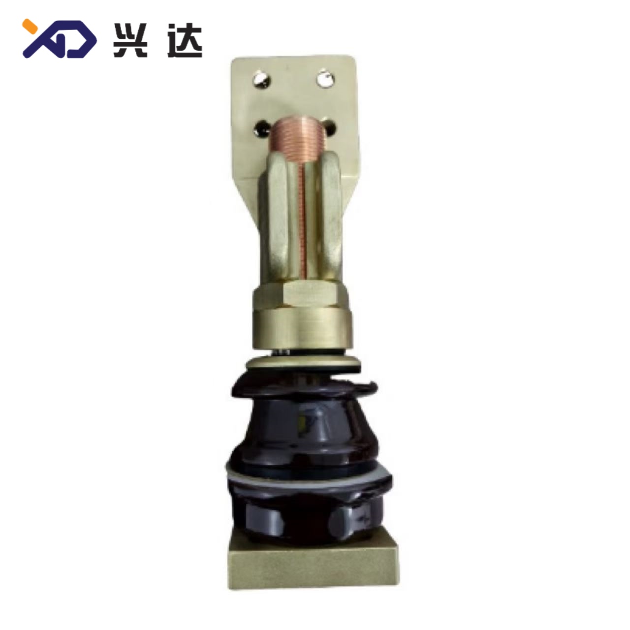
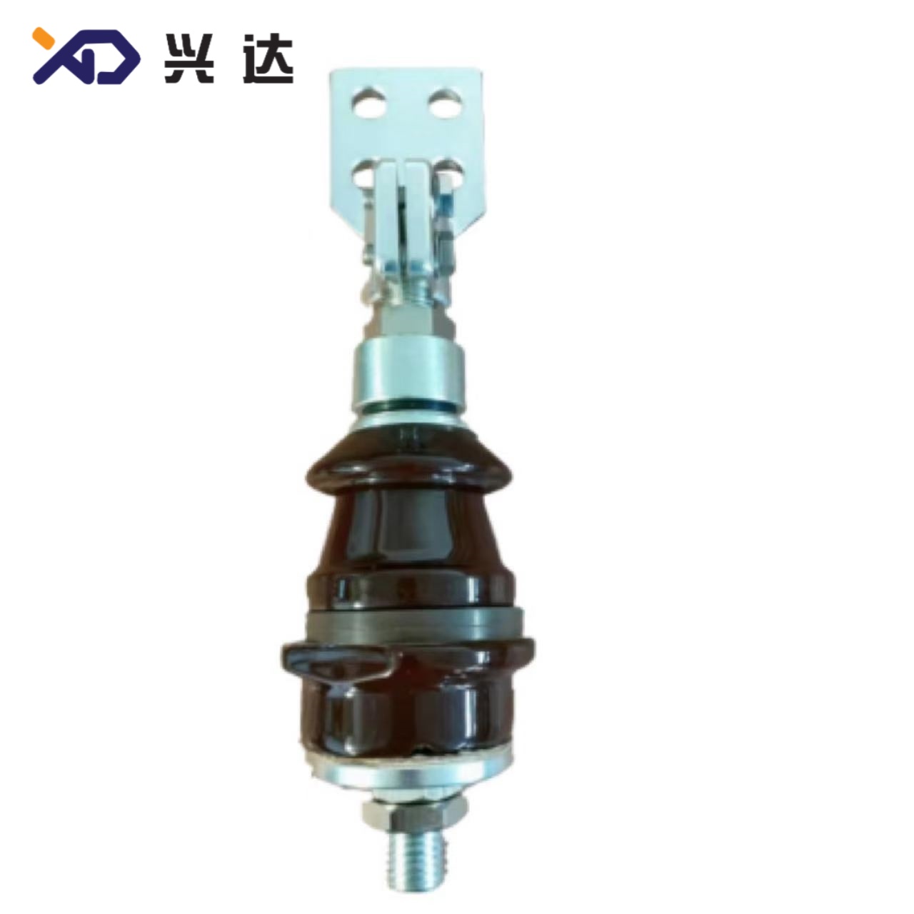
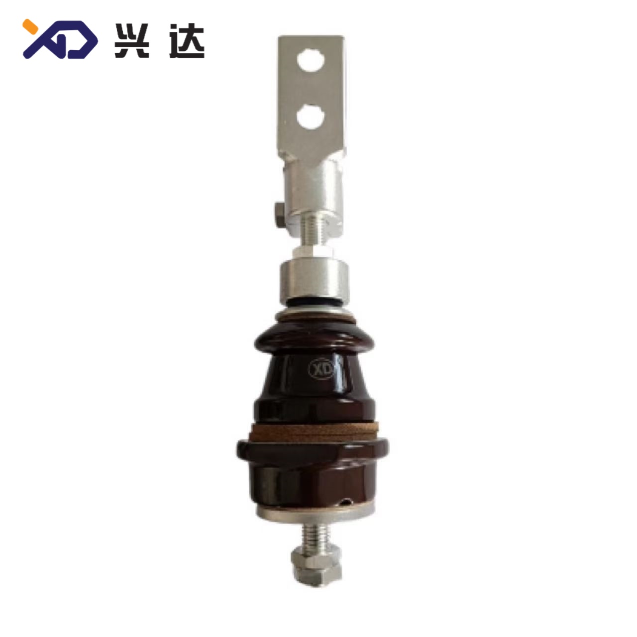
1.1 Definition of DIN Transformer BushingDIN transformer bushing is a standardized porcelain‑insulated through‑bushing for oil‑immersed transformers, designed following German DIN 42530, DIN 42533, DIN 42539 norms, widely harmonized with European EN 50386 and global IEC 60137 requirements. These components form the critical electrical transition point: they carry high‑current live conductors through the earthed metal transformer tank wall, maintain reliable dielectric isolation between energized copper conductors and the grounded tank housing, preserve oil‑tight sealing, and bear mechanical load from bus‑bar or cable connections.
Unlike custom‑built non‑standard bushings, DIN‑series transformer bushings enforce fixed mounting dimensions, tank opening cut‑out sizes, thread specifications, terminal layouts, dry‑arc distance and creepage distance values across different manufacturers. This strict dimensional standardization delivers mechanical interchangeability, a core advantage for European, Middle‑East, African and Asian transformer markets adopting DIN specifications.
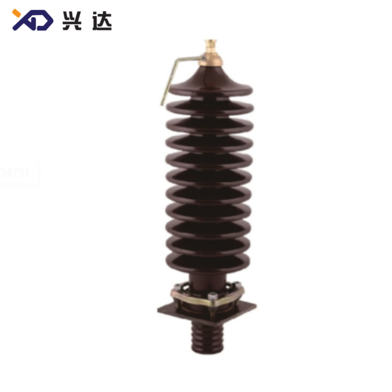
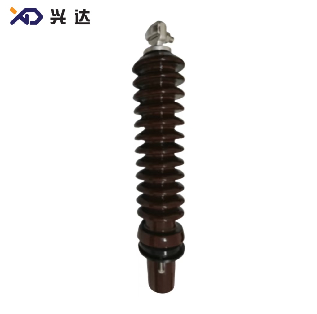
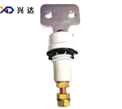
The typical DIN bushing assembly consists of glazed porcelain insulating shed body, central current‑carrying metallic conductor stem, upper air‑side connection terminal, lower oil‑side fitting, compression gaskets for tank sealing, and fastening nuts. The upper insulator section works exposed to atmospheric air; the lower portion sits fully immersed inside transformer mineral oil. Common keywords for SEO targeting: din transformer bushing, din standard bushing, din 42530 bushing, porcelain din bushing, oil immersed transformer bushing, low‑voltage din bushing, medium‑voltage din bushing.
1.2 Core Working PrincipleTwo critical insulation distances govern DIN bushing performance: dry‑arc (arcing) distance and creepage (creep) distance. Dry‑arc distance is the shortest straight‑line air clearance across the porcelain sheds, resisting lightning impulse and power‑frequency flash‑over through air. Creepage distance is the continuous surface path running over porcelain shed surfaces, which suppresses surface tracking and leakage current under polluted, humid, coastal or industrial outdoor operating environments.
The glazed electro‑porcelain body provides high dielectric strength, anti‑pollution surface performance and mechanical cantilever strength. Compressed rubber gaskets placed between bushing flange and transformer tank cover stop transformer oil leakage. The central threaded metallic stem conducts full rated load current; heat generated by resistive loss dissipates partly into surrounding transformer oil and partly to ambient air on the top terminal side. Improper dimension matching of tank opening, gasket compression torque or stem thread size is the most frequent root‑cause for oil‑leakage field failures of DIN‑type bushings.
1.3 Major Application Fields of DIN‑Standard Transformer BushingDIN‑compliant transformer bushings serve distribution and small‑medium power transformers across a broad voltage‑current scope: rated voltages range 1 kV up to 52 kV, rated current covers 250 A through 4500 A and above, supporting both new‑build transformer projects and in‑situ equipment retrofits and spare‑part replacement. Table 1 summarizes typical application sectors, voltage‑current ranges and dominant site‑specific operating stress.
表格
| Application Sector | Usual Rating Range | Key Operating Stress for DIN Bushing |
|---|---|---|
| Distribution Oil‑Immersed Transformers | 1‑36 kV / 250‑3150 A | Outdoor UV radiation, dust, rain pollution, cyclic thermal load |
| Industrial Plant Power Transformers | 12‑36 kV / 630‑4500 A | Industrial chemical dust, heavy cantilever load from copper bus‑bars |
| Renewable Energy Step‑Down Transformers (Solar / Wind Farm) | 12‑24 kV / 630‑2000 A | Coastal salt fog, large temperature swing, frequent load fluctuation |
| Transformer Retrofit & Maintenance Spare‑parts | 1‑52 kV / 250‑4500 A | Dimensional interchangeability requirement, existing tank opening constraint |
| Indoor Substation Unit Transformers | 1‑12 kV / 250‑3150 A | Limited pollution, focus on thermal performance and anti‑partial‑discharge property |
1.4 Core Terminology Explanation for DIN‑Bushing DatasheetWhen engineers read DIN‑bushing technical drawings and specification sheets, several dimension labels repeatedly appear:
- H: Overall total height of complete bushing assembly
- h1: Dry‑arc (arcing) distance, critical for impulse voltage withstand
- h2 / h3 / h4: Segment height dimensions for oil‑immersed section and flange mounting region
- Md: Thread size for upper and lower conductor stem
- d0: Tank‑cover opening hole diameter (critical mechanical dimension for installation)
- d1, d2, d3: Outer porcelain and flange related diameters
- a1×a2, a3×a4: Connection terminal mounting hole layout dimension for high‑current bus‑bar terminals
- t: Terminal plate thickness
- Creep distance: Total insulator surface creepage path length for anti‑pollution performance
- Shed (umbrella shield): Porcelain rain/shed structure, single‑shed or multi‑shed designs for different voltage grades
Note: Custom shaped specifications can be manufactured upon customer requirements, standard catalog dimensions serve as reference baseline only.
1.5 Why DIN‑Standard Interchangeability Matters in Global ProcurementMany global power‑system operators maintain transformer fleets originally built with DIN‑normed components. Without standardized DIN bushing dimensional norms, replacement spare‑parts would require custom machining of tank adapter plates, extending equipment downtime and raising retrofit cost significantly. DIN‑series bushing mechanical parameters (tank hole d0, stem thread Md, terminal hole pattern, flange thickness) are locked per voltage‑current class, so qualified DIN‑bushing alternatives fit existing tank cut‑out without modification work. Electrical performance still must comply with IEC 60137 test requirements for partial discharge, thermal cycle and impulse withstand even when mechanical dimensions follow DIN drawing standards.
Categories
Contact Us
Contact: Tianjin Delda Trading Co., Ltd
WhatsApp: +86 13662056855
Tel:
E-mail: solomon20210701@tjxddq.com
Add: Unit‑101, Workshop 3, Bozhong Automobile Industrial Park, No.5 Xianghui Road, Intersection of Xianghui Road and Gaoying Road, Beizhakou Town, Jinnan District, Tianjin, China