DIN Bushing
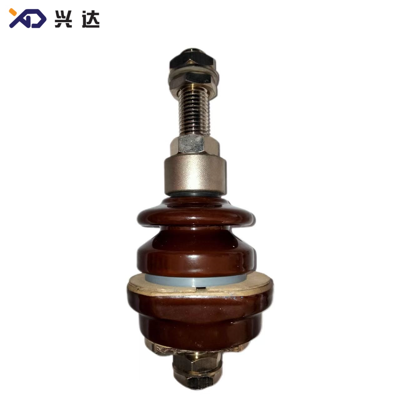
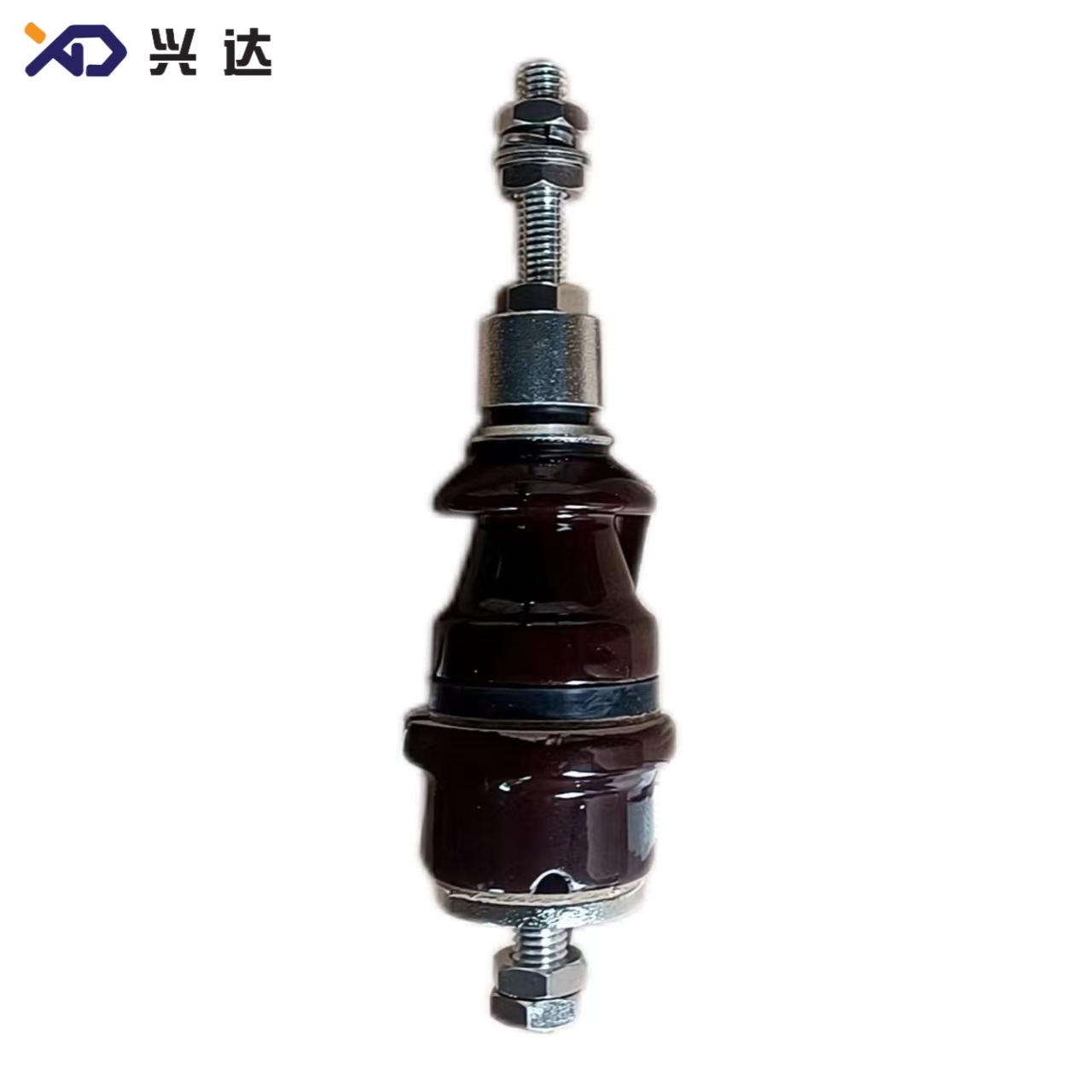
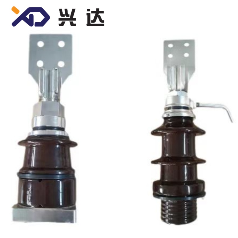
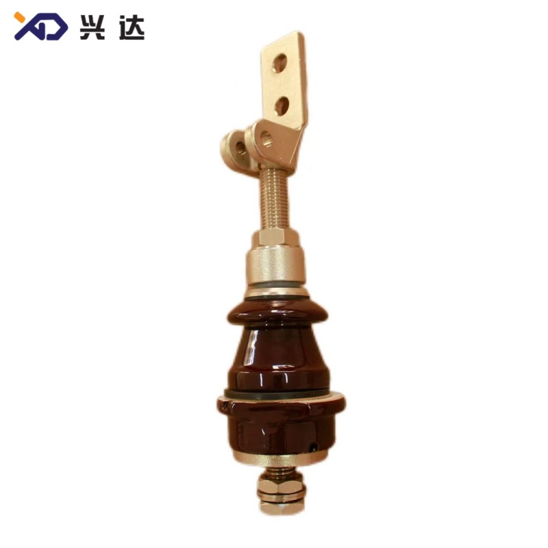
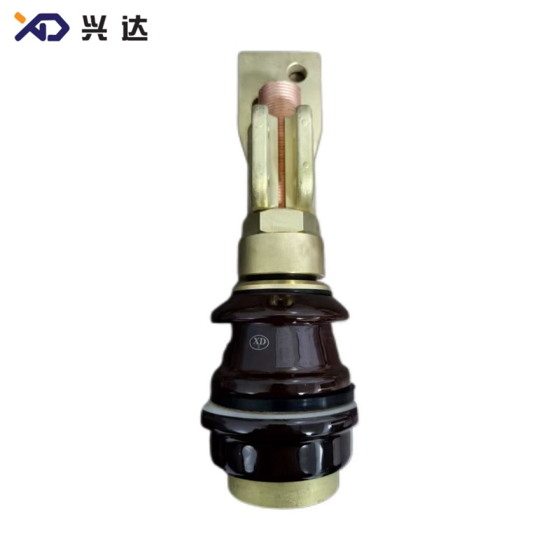
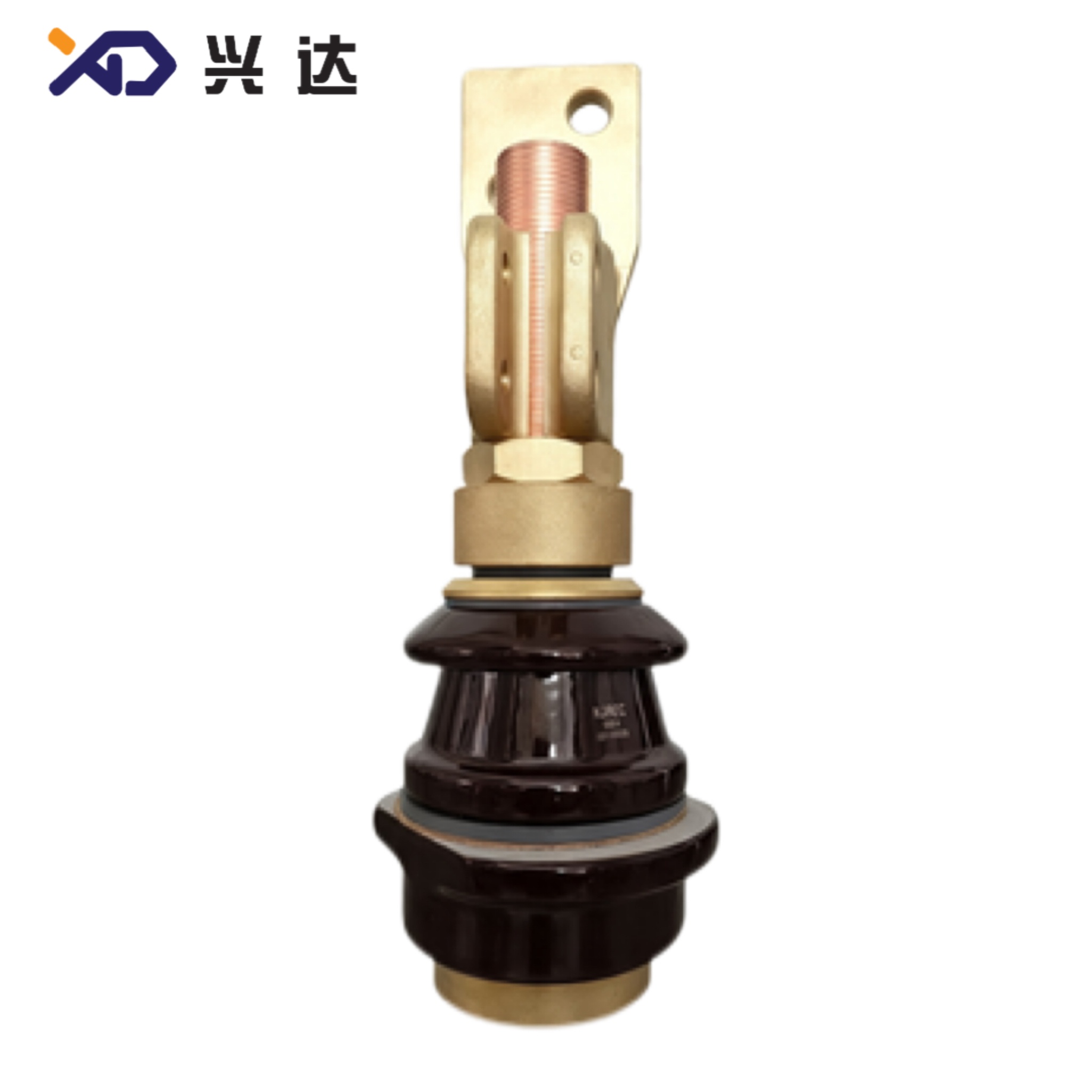
DIN Bushing Trusted Manufacturers, Suppliers and Exporters User-Approved Picks
DIN Bushing: Complete Technical Guide for DIN‑Standard Transformer Bushing
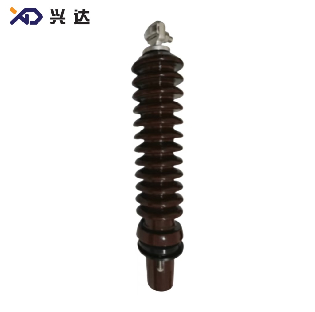
DIN bushing (DIN‑standard transformer bushing) is a widely‑adopted porcelain oil‑immersed transformer bushing series defined by German DIN industrial standards, harmonized with IEC 60137, EN 50180. Main reference documents include DIN 42530 (1 kV low‑voltage), DIN 42539 (3 kV low‑voltage), DIN 42531 / DIN 42533 for medium‑voltage 12‑52 kV draw‑lead and high‑current bushing designs. These components create an insulated, oil‑tight conductive path for energized winding conductors passing through the grounded metal tank wall of oil‑filled distribution and power transformers.
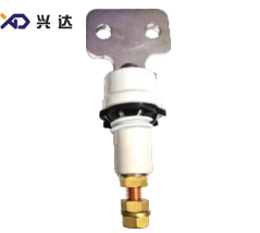
DIN‑standard bushings dominate Europe, Middle‑East, Africa and many Asia‑Pacific export‑oriented transformer projects. They are built with glazed alumina porcelain insulators, tin‑plated copper or brass conductive rods, metal flange assemblies and oil‑resistant NBR / HNBR sealing gaskets. Two major product categories are established: Low‑Voltage DIN Bushing (1 kV‑3 kV, 250 A‑4500 A) and Medium‑Voltage DIN Bushing (12 kV‑52 kV, 250 A‑3150 A), covering threaded‑connection type, cable‑through type and high‑current flag‑terminal constructions.
It is critical to note that DIN bushings are not mechanically interchangeable with Brazilian NBR‑standard bushings or North‑American ANSI bushings, even if voltage and current ratings appear numerically similar. Tank opening cut‑out, flange bolt patterns, terminal thread specifications and shed geometry differ completely; full dimensional drawings must be cross‑checked before any replacement or new‑build specification work.
Core Functions of DIN‑Standard Transformer Bushing
- Electrical Dielectric Insulation: Provides reliable galvanic isolation between live central conductor and earthed transformer tank, preventing phase‑to‑earth flash‑over, partial discharge and internal short‑circuit faults inside oil‑immersed transformers.
- Continuous Load‑Current Conduction: Transfers rated operating current between internal transformer windings and external overhead‑line or cable connections. Copper‑alloy conductive rods are dimensioned to limit temperature‑rise under continuous load and short‑time overload per DIN and IEC test requirements.
- Hermetic Oil‑Tight Sealing: Compressed elastomer gaskets between bushing flange and transformer tank block mineral‑oil leakage and stop moisture, dust and atmospheric pollutants from entering the transformer oil compartment, a key factor to extend transformer operational service life.
- Mechanical Load Endurance: DIN‑standard bushings are validated for cantilever bending stress, transportation vibration and thermal cycling. Standardized metric flange mounting patterns guarantee mechanical interchangeability for spare‑part field replacement across compliant manufacturers.
- Outdoor Pollution & Weather Withstand: Graded creepage‑distance options and multi‑shed porcelain geometry resist UV radiation, rain, condensation, industrial dust and coastal salt‑fog contamination for long‑term outdoor pole‑mounted and pad‑mounted transformer installations.
Key Advantages of DIN‑Standard Bushing
- Fully Standardized Metric Interfaces: DIN specifications fix all critical dimensions including tank opening diameter, flange bolt‑hole layout, terminal metric threads, arcing distance and creepage distance. This delivers cross‑manufacturer interchangeability and simplifies spare‑parts inventory management for utilities and transformer OEMs.
- Broad Rating Coverage: The complete portfolio spans low‑voltage 1 kV‑3 kV (250 A‑4500 A) and medium‑voltage 12 kV‑52 kV (250 A‑3150 A). Multiple mechanical construction variants (threaded stud, draw‑lead cable‑through, high‑current flag terminals) match different transformer design requirements.
- Proven Porcelain Insulation Performance: High‑grade brown‑glazed alumina porcelain insulator provides excellent tracking‑resistance, UV‑stability and long‑term ageing resistance for decades‑long outdoor service under cold, temperate and hot ambient climate conditionsMade-in-Ch....
- Harmonized International Test Protocols: Electrical withstand tests (power‑frequency dry‑wet withstand, lightning impulse BIL, partial‑discharge limits, temperature‑rise test) align with IEC 60137 international bushing standard, facilitating cross‑border project acceptance and third‑party type‑test certification.
- Modular Sealing & Termination Options: Standard NBR gaskets suit conventional mineral transformer oil; HNBR or FKM sealing material options are available for biodegradable vegetable‑ester dielectric fluids. Air‑side terminals can be threaded‑stud, draw‑lead cable‑through or flag‑type palm lugs according to project‑specific connection hardware.
- Predictable Total Cost of Ownership: DIN‑standard bushings have decades‑long field‑proven service life in global installed transformer fleets. Standardized dimensions reduce custom‑engineering overhead for transformer designers and minimize on‑site installation error risks on production lines.
Standard Operating Conditions for DIN‑Standard Bushing
DIN‑specification transformer bushings are designed for oil‑immersed distribution and medium‑size power transformers under these nominal service conditions:
- Ambient operating temperature range: ‑40 °C up to +45 °C
- Reference installation altitude: ≤ 1000 m above sea‑level. For installation above 1000 m, creepage distance and insulation withstand level must be up‑rated to compensate reduced air dielectric strength at high elevation locations.
- Permitted installation inclination: maximum 30° deviation from vertical mounting axis.
- Service environment: outdoor pole‑mounted transformers, pad‑mounted distribution transformers, indoor transformer rooms; extended‑creepage anti‑pollution variants are mandatory for coastal salt‑fog zones and heavy‑industrial pollution sites.
- Nominal power‑system frequency: 50 Hz; suitable also for 60 Hz power‑grid applications with appropriate type‑test validation.
Engineering Note: Custom‑modified dimensions, extended creepage profiles and special terminal configurations can be engineered for non‑standard project requirements, but custom variants lose full cross‑manufacturer interchangeability.
DIN Bushing Technical Specification Tables
All dimension values in millimetres. Data compiled from standard DIN‑series bushing dimensional drawings for oil‑immersed transformers. Model naming convention:
DIN‑Voltage/Current. H = overall total height; Md = thread specification; d0 = tank opening diameter; h1 = arcing (dry‑arc) distance; creep distance = surface creepage path over porcelain shed surface; shield = number of porcelain sheds; weight = assembly weight in kg.
Table 1: Low‑Voltage DIN Bushing (1 kV / 3 kV, 250 A‑630 A)
表格
| Code | Model | Rated Voltage | Rated Current(A) | H | h2 | h3 | Md Thread | d1 | d2 | d3 | d0 Tank Opening | h1 Arcing Distance | Creep Distance | Shield (Sheds) | Weight (kg) |
|---|---|---|---|---|---|---|---|---|---|---|---|---|---|---|---|
| XD.0250.1.DIN | DIN‑1/250 | 1 kV | 250 | 205 | 62.5 | 28.5 | M12×1.75 | 50 | 60 | 50 | 28 | 49 | 55 | 1 single shed | 1.0 |
| XD.0400.1.DIN | DIN‑1/400 | 1 kV | 400 | 260 | 78 | 43 | M16×2.0 | 70 | 85 | 70 | 45 | 59 | 70 | 1 single shed | 1.6 |
| XD.0630.1.DIN | DIN‑1/630 | 1 kV | 630 | 260 | 78 | 43 | M20×2.5 | 70 | 85 | 70 | 45 | 59 | 70 | 1 single shed | 2.4 |
| XD.0250.3.DIN | DIN‑3/250 | 3 kV | 250 | 272 | 87.5 | 28.5 | M12×1.75 | 75 | 70 | 60 | 39 | 89 | 120 | 1 single shed | 1.5 |
| XD.0400.3.DIN | DIN‑3/400 | 3 kV | 400 | 318 | 103 | 43 | M16×2.0 | 90 | 85 | 70 | 39 | 89 | 120 | 1 single shed | 1.9 |
| XD.0630.3.DIN | DIN‑3/630 | 3 kV | 630 | 318 | 103 | 43 | M20×2.5 | 90 | 85 | 70 | 45 | 89 | 120 | 1 single shed | 2.9 |
Table 2: Low‑Voltage High‑Current DIN Bushing (1 kV / 3 kV, 1000 A‑4500 A)
表格
| Code | Model | Rated Voltage | Rated Current(A) | H | h2 | h3 | Md Thread | d1 | d2 | d0 Tank Opening | h1 Arcing Distance | Creep Distance | Shield (Sheds) | Weight (kg) |
|---|---|---|---|---|---|---|---|---|---|---|---|---|---|---|
| XD.1000.1.DIN | DIN‑1/1000 | 1 kV | 1000 | 324 | 58 | 17 | M30×2.0 | 90 | 110 | 56 | 57 | 75 | 1 single shed | 5.5 |
| XD.2000.1.DIN | DIN‑1/2000 | 1 kV | 2000 | 405 | — | 22 | M42×3.0 | 104 | 125 | 60 | 58 | 70 | 1 single shed | — |
| XD.3150.1.DIN | DIN‑1/3150 | 1 kV | 3150 | 434 | 68 | 27 | M48×3.0 | 125 | 150 | 60 | 57 | 75 | 1 single shed | 16.5 |
| XD.1000.3.DIN | DIN‑3/1000 | 3 kV | 1000 | 372 | 78 | 17 | M30×2.0 | 110 | 110 | 56 | 87 | 120 | 1 single shed | 6.5 |
| XD.2000.3.DIN | DIN‑3/2000 | 3 kV | 2000 | 460 | 83 | 22 | M42×3.0 | 125 | 125 | 60 | 89 | 120 | 1 single shed | — |
| XD.3150.3.DIN | DIN‑3/3150 | 3 kV | 3150 | 495 | 88 | 27 | M48×3.0 | 145 | 150 | 60 | 88 | 120 | 1 single shed | 18.7 |
| XD.4500.3.DIN | DIN‑3/4500 | 3 kV | 4500 | 560 | 101 | 30 | M55×3.0 | 175 | 160 | 100 | 95 | 125 | 1 single shed | 33.5 |
Table 3: Medium‑Voltage DIN Bushing (12 kV‑52 kV, 1000 A‑3150 A High‑Current Series)
表格
| Code | Model | Rated Voltage | Rated Current(A) | H | h2 | h3 | Md Thread | d1 | d3 | d0 Tank Opening | h1 Arcing Distance | Creep Distance | Shield (Sheds) | Weight (kg) |
|---|---|---|---|---|---|---|---|---|---|---|---|---|---|---|
| XD.1000.12.DIN | DIN‑12/1000 | 12 kV | 1000 | 637 | 175 | 85 | M30×2.0 | 170 | 108 | 115 | 166 | 340 | 2 single sheds | 18 |
| XD.2000.12.DIN | DIN‑12/2000 | 12 kV | 2000 | 737 | 205 | 115 | M42×3.0 | 170 | 131 | 135 | 166 | 350 | 2 single sheds | — |
| XD.3150.12.DIN | DIN‑12/3150 | 12 kV | 3150 | 772 | 215 | 125 | M48×3.0 | — | 131 | 135 | 166 | 350 | 2 single sheds | 29 |
| XD.1000.24.DIN | DIN‑24/1000 | 24 kV | 1000 | 722 | 185 | 85 | M30×2.0 | 185 | 108 | 115 | 241 | 500 | 3 single sheds | 18 |
| XD.2000.24.DIN | DIN‑24/2000 | 24 kV | 2000 | 822 | 215 | 115 | M42×3.0 | 210 | 131 | 135 | 241 | 500 | 3 single sheds | 29 |
| XD.3150.24.DIN | DIN‑24/3150 | 24 kV | 3150 | 857 | 225 | 125 | M48×3.0 | 210 | 131 | 135 | 241 | 500 | 3 single sheds | 33 |
| XD.1000.36.DIN | DIN‑36/1000 | 36 kV | 1000 | 852 | 210 | 85 | M30×2.0 | 175 | 108 | 115 | 346 | 640 | 4 single sheds | 22 |
| XD.2000.36.DIN | DIN‑36/2000 | 36 kV | 2000 | 952 | 240 | 115 | M42×3.0 | 230 | 131 | 135 | 346 | 750 | 4 single sheds | 35 |
| XD.3150.36.DIN | DIN‑36/3150 | 36 kV | 3150 | 987 | 250 | 125 | M48×3.0 | 230 | 131 | 135 | 346 | 750 | 4 single sheds | 40 |
| XD.1000.52.DIN | DIN‑52/1000 | 52 kV | 1000 | 1012 | 280 | 100 | M30×2.0 | 250 | 131 | 135 | 432 | 950 | 6 single sheds | 36 |
| XD.2000.52.DIN | DIN‑52/2000 | 52 kV | 2000 | 1112 | 310 | 130 | M42×3.0 | 250 | 131 | 135 | 432 | 950 | 6 single sheds | 45 |
| XD.3150.52.DIN | DIN‑52/3150 | 52 kV | 3150 | 1147 | 320 | 140 | M48×3.0 | 250 | — | 135 | 432 | 950 | 6 single sheds | 50 |
Table 4: DIN‑Standard Bushing vs Brazilian NBR‑Standard Bushing Comparison
表格
| Comparison Parameter | DIN‑Standard Transformer Bushing | Brazilian NBR‑Standard Transformer Bushing |
|---|---|---|
| Governing Core Standards | DIN 42530 / 42531 / 42533; IEC 60137, EN 50180 | ABNT NBR 16856 (LV), ABNT NBR 5435 (MV) |
| Primary Target Market | Europe, Middle‑East, Africa, Asia‑Pacific export projects | Brazil and Latin‑American NBR‑compliant power markets |
| Low‑Voltage Typical Ratings | 1 kV‑3 kV; 250 A‑4500 A | 1.3 kV; 160 A‑800 A |
| Medium‑Voltage Typical Ratings | 12 kV‑52 kV; 250 A‑3150 A | 15 kV / 24.2 kV / 36.2 kV; 160 A |
| Mounting Interface | DIN‑defined metric flange bolt‑hole patterns and tank opening dimensions | Exclusive NBR‑defined tank opening, flange layout and terminal threads |
| Porcelain Shed Geometry | Optimized for European pollution‑class specifications | Optimized for Brazilian coastal salt‑fog & inland industrial pollution |
| Physical Interchangeability | Zero direct interchangeability with NBR bushing | Zero direct interchangeability with DIN bushing |
Critical Parameter Checklist for DIN Bushing Selection
When specifying new‑build transformers or ordering replacement spare‑part DIN bushings, electrical designers and procurement engineers must validate these key technical parameters to avoid costly specification errors:
- Rated Voltage Class: Must strictly match transformer winding operating voltage. Low‑voltage DIN bushings serve transformer secondary circuits (1 kV / 3 kV). Medium‑voltage DIN bushings are used for primary‑side 12 kV, 24 kV, 36 kV or 52 kV distribution‑transformer terminals. Never apply a lower‑voltage‑class bushing to higher‑voltage service conditions.
- Rated Continuous Current: Select current rating with recommended 10‑20 % thermal safety margin above maximum expected transformer operating load. DIN low‑voltage current grades extend as high as 4500 A for large distribution transformers, while medium‑voltage DIN bushings commonly run 250 A‑3150 A range. High‑current models adopt flag‑type palm terminals for busbar connection.
- Creepage Distance, Arcing Distance & Pollution Class: External surface creepage path length and dry‑arcing clearance on porcelain insulator are decisive for anti‑flash‑over performance under polluted atmospheric conditions. For coastal salt‑fog, heavy industrial dust or high‑altitude installation locations, specify upgraded extended‑creepage variants instead of base‑standard creepage values, following IEC 60815 pollution‑class guidelines.
- Full Mechanical Dimensional Verification: Cross‑check tank‑opening cut‑out diameter d0, flange bolt‑hole circle diameter, number & size of flange mounting holes, total bushing height H, air‑side exposed height h1, oil‑immersed segment height h2‑h3, upper‑side external‑connection thread Md and internal transformer‑side lower terminal thread. Even minor dimension mismatch will cause installation failure, oil‑leak risk or mechanical‑stress damage on insulator body.
- Sealing‑Gasket Material Compatibility: Standard NBR rubber gaskets are compatible with conventional mineral transformer oil. For transformers filled with biodegradable vegetable‑ester dielectric oil, specify HNBR or FKM fluorocarbon sealing material, to prevent gasket swelling, ageing and premature seal‑failure faults.
- Termination Configuration: Confirm air‑side connection type (threaded‑stud, draw‑lead cable‑through, flag‑type palm lugs) matches cable or busbar connection hardware on‑site. Medium‑voltage DIN bushings are available in cable‑through draw‑lead construction or rigid threaded‑stud construction for different transformer internal lead‑out arrangements.
DIN Bushing Installation & Field Maintenance Best Practices
- Pre‑Installation Visual Inspection: Before mounting onto transformer tank, carefully inspect porcelain insulator surface for cracks, chips or glaze damage; examine copper / brass metal terminals for corrosion or thread damage; verify sealing gasket surface free of scratches, dirt and ageing degradation. Damaged bushings must never be installed on energized or soon‑to‑be‑energized transformers.
- Gasket Mounting Rules: Always install brand‑new, undamaged sealing gaskets between bushing flange and transformer tank flange; never reuse old compressed gaskets removed from previously‑operated bushings. Apply bolt‑torque in cross‑tightening sequence across all flange mounting bolts to achieve uniform gasket compression; uneven bolt torque is one of the leading root‑causes of slow transformer‑oil leakage at bushing flange joints.
- Controlled Torque for Conductive Terminals: Apply manufacturer‑specified torque values both for upper external cable‑connection nuts and lower internal transformer‑winding connection terminals. Over‑torque may strip copper threads or crack porcelain; insufficient torque will create high‑resistance contact joints leading to dangerous thermal over‑heating under load current.
- Limit Cantilever Mechanical Load: Connected external cables and busbars must not impose excessive sideways bending force to bushing top terminals. Heavy cable weight must be supported by independent mechanical cable‑support clamps, to avoid permanent porcelain insulator fracture caused by long‑term cantilever stress. This requirement is especially important for high‑current flag‑terminal DIN bushings for 1000 A‑3150 A service.
- Periodic Routine Maintenance during Transformer Service Cycles: During scheduled transformer outages, inspect flange‑gasket area for oil‑leak traces. Check porcelain outer surface for heavy dust, salt‑deposit or industrial‑contaminant accumulation; clean contaminated insulator surfaces to preserve effective creepage performance. Check connection terminals for thermal discoloration and corrosion signs.
- De‑energized‑Only Bushing Replacement: All DIN‑bushing removal, maintenance and replacement work must be executed on fully de‑energized and properly‑grounded transformer equipment. Live‑line replacement operations are not permitted for this category of oil‑immersed porcelain transformer bushings.
Main Application Scenarios for DIN‑Standard Transformer Bushings
- Oil‑immersed pole‑mounted and pad‑mounted distribution transformers built to European DIN‑IEC technical specifications
- Medium‑size power transformers for industrial facilities, commercial power‑supply substations
- Transformer OEM production for export projects targeting Europe, Middle‑East, Africa and Southeast‑Asia markets requiring DIN‑standard component interfaces
- Utility‑owned transformer‑fleet spare‑parts inventory and field repair replacement work
- Renewable‑energy step‑up transformers for wind‑farm and solar‑farm distribution substations following European equipment specifications.
Common Field‑Failure Troubleshooting for DIN‑Standard Bushings
- Oil Leakage at Bushing‑Flange Joint: Typical root‑causes include reused old gasket, uneven bolt tightening torque, gasket mechanical scratch or deformation during assembly. Recommended remedy: fully replace sealing gasket; tighten flange bolts in cross‑pattern sequence to achieve uniform compression.
- Outdoor Surface Flash‑Over Faults: Root‑causes are insufficient creepage distance for site pollution severity, heavy contaminant accumulation on porcelain sheds, or installation at altitude higher than rated without up‑graded insulation design. Remedy: select higher‑creepage anti‑pollution DIN bushing variant; implement regular insulator‑cleaning maintenance schedule for heavily‑polluted sites.
- Terminal Over‑heating under Operating Load: Triggered by insufficient terminal tightening torque, corroded contact surfaces, or undersized bushing current rating versus real‑world operating load. Remedy: perform maintenance during transformer de‑energized condition, clean contact surfaces and retorque terminals; re‑validate current‑rating selection including thermal safety margin.
- Porcelain Insulator Cracking or Chipping: Root‑causes are mechanical impact damage during transportation or installation, excessive cantilever side‑load weight from connected cables, or rapid thermal‑shock events. Remedy: handle bushing assemblies carefully during logistics and installation; deploy separate cable‑support hardware to eliminate sideways mechanical stress on bushing upper terminals.
Conclusion
DIN‑standard transformer bushings are mission‑critical insulating components for oil‑immersed transformers deployed across European and many global export‑oriented power‑system markets. The complete DIN bushing portfolio covers low‑voltage 1 kV‑3 kV ratings (250 A‑4500 A) and medium‑voltage 12 kV‑52 kV ratings (250 A‑3150 A), governed by well‑documented DIN specifications harmonized with IEC 60137 international bushing standard. Multiple mechanical constructions including threaded‑stud, draw‑lead cable‑through and high‑current flag‑terminal designs satisfy diverse transformer‑internal lead‑out architectures.
Correct product specification requires careful matching of rated voltage, continuous current rating, creepage‑distance for pollution and altitude service conditions, plus comprehensive mechanical dimensional cross‑check for transformer‑tank mounting interfaces. Proper gasket material selection, controlled‑torque installation practices and scheduled periodic maintenance work are essential steps to maximize DIN bushing service life and prevent avoidable transformer outages caused by bushing‑related faults.
Categories
Contact Us
Contact: Tianjin Delda Trading Co., Ltd
WhatsApp: +86 13662056855
Tel:
E-mail: solomon20210701@tjxddq.com
Add: Unit‑101, Workshop 3, Bozhong Automobile Industrial Park, No.5 Xianghui Road, Intersection of Xianghui Road and Gaoying Road, Beizhakou Town, Jinnan District, Tianjin, China