ANSI Bushing
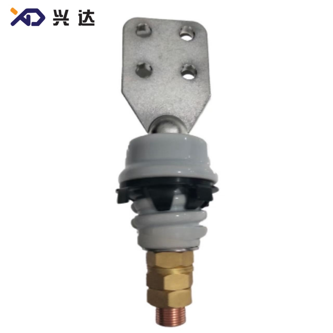
ANSI Transformer Bushing – Complete Technical Reference Guide
ANSI Transformer Bushing – Complete Technical Reference Guide
ANSI Transformer Bushing – Definition, Standards, Specifications, Material Comparison and Application Guidance
Introduction to ANSI Transformer Bushing
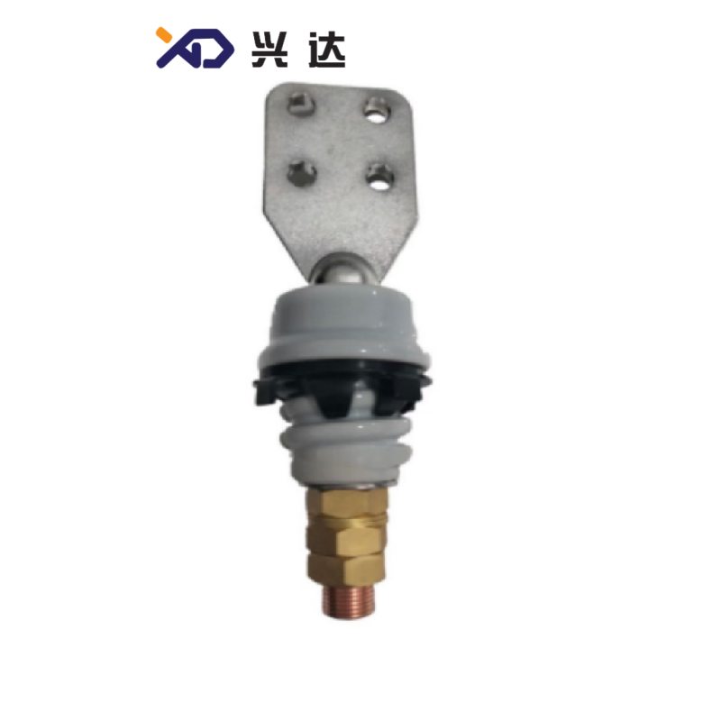
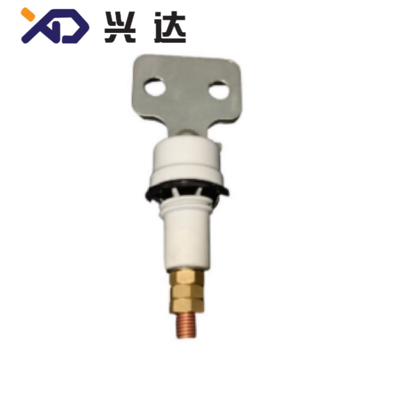
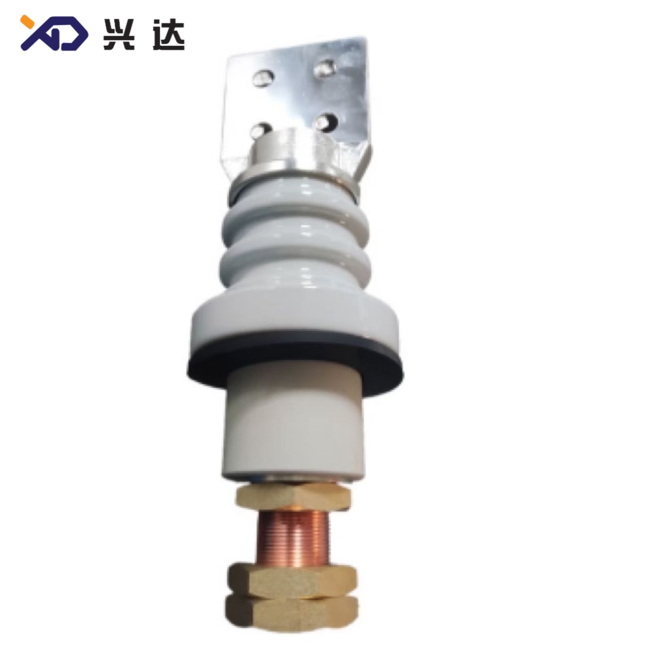
An ANSI transformer bushing, also widely shortened as ANSI bushing, is a critical insulating penetration component built according to American National Standards Institute and IEEE specifications for oil‑immersed distribution and power transformers deployed throughout North‑American power grids. An ANSI bushing passes energized internal winding conductors through the grounded metal transformer tank wall, delivering two core functions: high‑voltage electrical isolation and robust mechanical connection for external overhead or busbar terminations.
Unlike DIN‑standard or IEC‑standard transformer bushings designed for European and global markets, ANSI bushings follow North‑American dimensional conventions, imperial thread formats (UNC / UNF), standardized creepage distance requirements, BIL (Basic Insulation Level) ratings, and mandatory type‑test protocols defined in ANSI‑C29 series and IEEE C57.19 standardsThomas Ele.... Most ANSI bushings serve pad‑mount transformers, pole‑mount distribution transformers, and medium‑voltage power transformers operating on 60‑Hz utility networks.
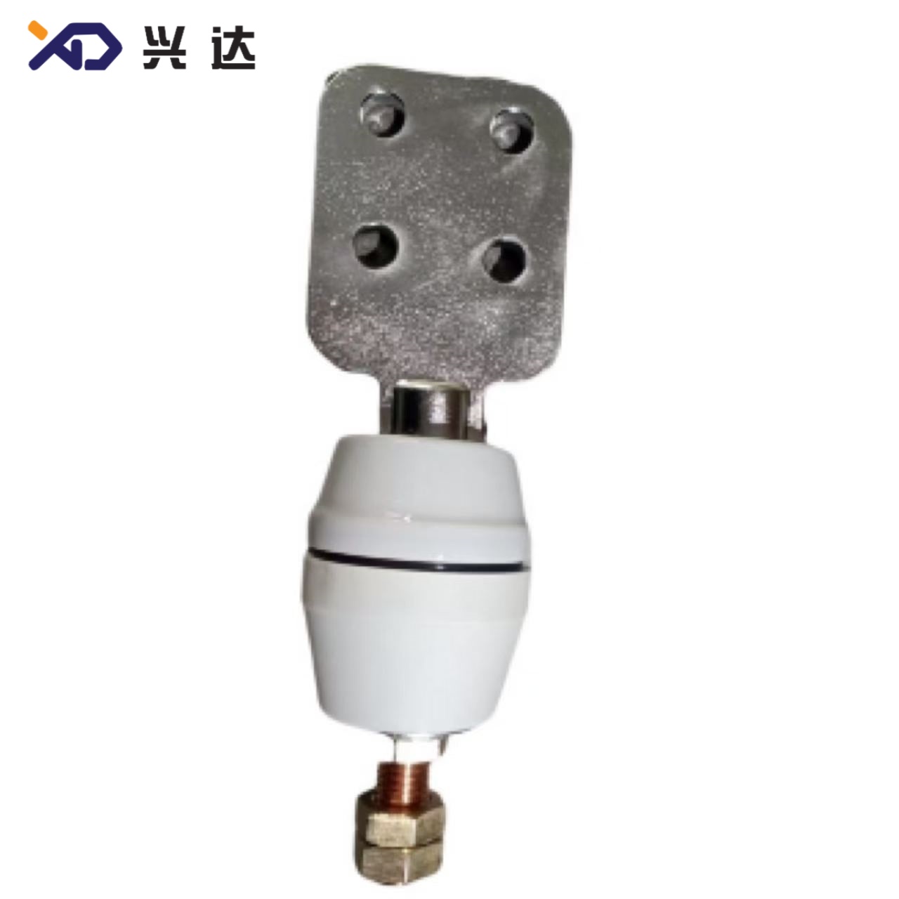
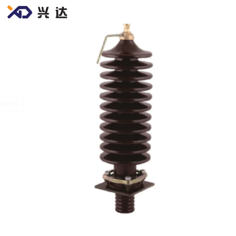
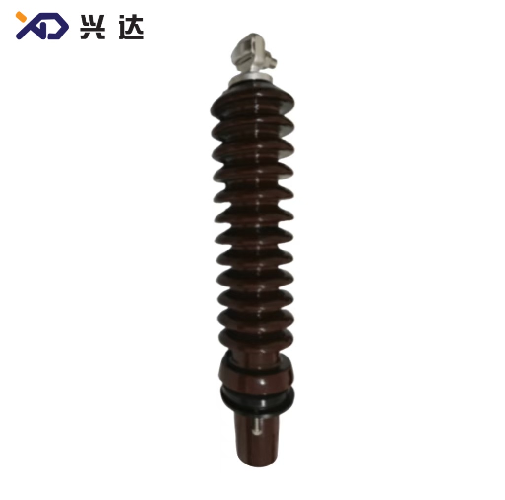
Two primary material families dominate the ANSI bushing market: porcelain ANSI bushings and epoxy‑resin ANSI bushings. Porcelain ANSI transformer bushings represent the long‑established mainstream choice for general‑purpose oil‑immersed transformer installations. Epoxy‑resin ANSI bushings deliver enhanced anti‑pollution performance, higher impact toughness, and reduced maintenance requirements for coastal salt‑fog zones and heavy‑industrial contaminated environments.
Every ANSI bushing must simultaneously satisfy four core functional demands during its operational lifespan. First, it must maintain reliable dielectric insulation between live high‑potential conductors and the grounded transformer tank, suppressing leakage current and preventing surface flashover under normal voltage and lightning impulse surges. Second, it supplies mechanical support for connection terminals, resisting cantilever stress from heavy cables, wind loads, ice accumulation, and installation torque. Third, it creates a leak‑tight tank penetration seal to retain transformer mineral oil and block ingress of moisture, dust, and airborne pollutants. Fourth, its structural design permits effective heat dissipation for load‑carrying central conductors, avoiding thermal degradation of insulating materials under continuous rated‑current operationIEEE Techn....
Governing Industry Standards for ANSI Bushing
Compliance with formal ANSI and IEEE standards forms the baseline for interchangeability, safety, and field reliability of ANSI transformer bushings.
| Standard Designation | Subject Scope |
|---|---|
| ANSI C29.1 / C29.2 | Porcelain insulator general requirements, mechanical strength, glaze, shed geometry, creepage distance |
| IEEE C57.19.00 / C57.19.01 | Transformer bushing electrical testing: power‑frequency withstand, partial‑discharge limits, short‑circuit thermal and dynamic resistance, BIL rating rulesThomas Ele... |
| ANSI C29.13 | Composite / epoxy‑resin bushing material and performance requirements |
All ANSI‑compliant transformer bushings must complete defined type tests before field deployment, including dry and wet power‑frequency withstand voltage test, partial‑discharge measurement, cantilever mechanical load test, thermal cycling test, and oil‑tight leakage test. Compliance ensures cross‑manufacturer interchangeability when voltage, current, mounting flange footprint, and thread specifications match. Utility operators benefit from simplified spare‑parts management and shorter transformer downtime during maintenance or component replacement.
Key Technical Specification Tables for ANSI Porcelain Transformer Bushings
General Parameter Overview for ANSI‑Series Transformer Bushings
| Parameter | Typical Value Range | Remarks |
|---|---|---|
| Rated System Frequency | 60 Hz | North‑American grid requirement |
| Rated Voltage Classes | 5 kV, 10 kV, 15 kV, 25 kV, 34.5 kV | Covers distribution‑transformer high‑voltage and low‑voltage sides |
| Rated Continuous Current | 55 A ~ 6000 A | Terminal style shifts from eyebolt to spade‑pad at higher amperage |
| Insulation Housing Material | High‑grade porcelain / epoxy resin composite | Porcelain dominates 15‑34.5 kV distribution applications |
| Mounting Method | Flange‑mount onto transformer tank opening | Imperial UNC / UNF threaded studs and bolt holes |
| Creepage Distance | 330 mm ~ 406.4 mm | Depends on voltage class and pollution grade |
| Applicable Transformer Type | Oil‑immersed pole‑mount, pad‑mount, distribution power transformer | Not intended for gas‑filled transformers without modification |
| Operating Ambient Temperature | −40 °C ~ +45 °C | Standard service condition |
Extracted Dimensional & Performance Table for 15 kV‑25 kV ANSI Porcelain Bushings
| Model Designation | Shed Type | Overall Height H (mm) | h1 (mm) | h2 (mm) | Thread Md | Terminal Width B (mm) | Bolt Hole Pattern | Plate Thickness t (mm) | Creepage Distance (mm) | Internal Code Reference |
|---|---|---|---|---|---|---|---|---|---|---|
| ANSI‑15KV‑125A‑2‑hole | 6 single shed | 339 | 233 | 39 | 3/8‑16 UNC | 76.2 | 2×Ø14.3 | 6.35 | 330 | 12XD.401.G13‑B |
| ANSI‑15KV‑125A‑4‑hole | 6 single shed | 409 | 233 | 39 | 3/8‑16 UNC | 89 | 4×Ø14.3 | 12.7 | 330 | 12XD.401.G13‑I |
| ANSI‑15KV‑250A‑2‑hole | 6 single shed | 339 | 233 | 39 | 1/2‑13 UNC | 76.2 | 2×Ø14.3 | 6.35 | 330 | 12XD.401.G13‑C |
| ANSI‑15KV‑250A‑4‑hole | 6 single shed | 409 | 233 | 39 | 1/2‑13 UNC | 89 | 4×Ø14.3 | 12.7 | 330 | 12XD.401.G13‑O |
| ANSI‑15KV‑250A‑6‑hole | 6 single shed | 452.5 | 233 | 39 | 1/2‑13 UNC | 89 | 6×Ø14.3 | 12.7 | 330 | 12XD.401.G13‑M |
| ANSI‑15KV‑417A‑2‑hole | 6 single shed | 339 | 233 | 39 | 5/8‑11 UNC | 76.2 | 2×Ø14.3 | 6.35 | 330 | 12XD.401.G13‑E |
| ANSI‑15KV‑417A‑6‑hole | 6 single shed | 452.5 | 233 | 39 | 5/8‑11 UNC | 89 | 6×Ø14.3 | 12.7 | 330 | 12XD.401.G13‑J |
| ANSI‑25KV‑417A‑4‑hole | 7 single shed | 433 | 254 | 43 | 5/8‑11 UNC | 89 | 4×Ø14.3 | 12.7 | 406.4 | 12XD.401.A08 |
| ANSI‑25KV‑417A‑6‑hole | 7 single shed | 477 | 254 | 43 | 5/8‑11 UNC | 89 | 6×Ø14.3 | 12.7 | 406.4 | 12XD.401.A07 |
Material Comparison: Porcelain ANSI Bushing vs Epoxy‑Resin ANSI Bushing
| Evaluation Item | Porcelain ANSI Transformer Bushing | Epoxy‑Resin ANSI Transformer Bushing |
|---|---|---|
| Long‑Term Insulation Performance | Excellent stable dielectric property for decades | Very good; superior hydrophobic anti‑pollution surface |
| Mechanical Shock Resistance | High compressive strength; brittle against sharp impact | Higher toughness, resistant to chipping and cracking |
| Surface Pollution Performance | Requires periodic cleaning in coastal / industrial sites | Low‑maintenance, anti‑tracking for contaminated environments |
| Unit Weight | Relatively heavy | Lighter weight, reduces flange mechanical load |
| UV‑Aging Resistance | Outstanding glaze UV stability | Good with UV‑formulated epoxy grades |
| Typical Service Life (normal environment) | 20‑30 years | 25‑35 years |
| Primary Application Scenario | Standard inland oil‑immersed distribution transformers | Coastal salt‑fog, chemical‑plant, heavy‑dust industrial zones |
Core Advantages of ANSI‑Standard Transformer Bushings
ANSI‑designed transformer bushings deliver multiple engineering benefits for North‑American power‑system operators. First, standardized ANSI / IEEE specifications guarantee predictable electrical performance. Every qualified ANSI bushing is engineered to control partial‑discharge magnitudes within strict limits under continuous operating voltage. Creepage‑distance values are calculated according to ANSI pollution‑classification rules to mitigate surface flashover triggered by salt deposits, industrial dust, and dew or rain wetting conditionsHewei Powe....
Second, ANSI bushing designs prioritize mechanical reliability and sealing integrity. Mounting‑flange dimensions match standard transformer tank cut‑out sizes for North‑American distribution units. When paired with oil‑resistant nitrile or Viton gaskets and correct diagonal‑pattern bolt torquing procedures, ANSI bushings minimize transformer‑oil leakage risk. Terminal connections follow defined imperial‑thread torque limits to prevent loose contacts and dangerous overheating under full‑load current conditionsNJREC.
Third, wide environmental adaptability makes ANSI bushings suitable for diverse climate zones across the United States, Canada, and other regions adopting 60‑Hz ANSI power equipment. Properly‑specified ANSI porcelain and epoxy‑resin bushings withstand freezing low‑temperature winters, high‑temperature summer heat, and large diurnal temperature swings without accelerated material aging.
Fourth, dimensional standardization delivers practical operational advantages: physical interchangeability. As long as rated voltage, rated continuous current, flange hole layout, thread specifications, and tank‑opening dimensions align, ANSI transformer bushings from different manufacturers can substitute for one another during transformer repair or retrofitting. This interchangeability lowers spare‑part inventory burden for utility fleets and cuts equipment outage duration.
Heading 2 (16pt): Installation, Operation and Preventive‑Maintenance Best Practices for ANSI Bushings
Even fully‑compliant ANSI transformer bushings can suffer premature failure caused by improper handling, incorrect mounting torque, or poor maintenance workflows. Pre‑installation visual inspection represents the first critical checkpoint. Technicians must examine porcelain or epoxy surfaces for chipping, cracks, glaze damage, and inspect all sealing gaskets for aging or physical damage. Damaged bushings should never be fitted onto transformers; invisible micro‑cracks in porcelain will gradually propagate under thermal cycling and oil pressure, eventually causing dielectric breakdown and oil leakage.
During installation, mounting‑flange bolts must be tightened slowly using a star‑shaped or diagonal cross‑torquing sequence. Uneven one‑direction bolt tightening creates tilted flange loading, generates hidden mechanical stress on the insulator body, crushes part of the sealing gasket while leaving other sections insufficiently compressed, and opens leakage pathways for transformer oil. Over‑torquing represents one of the most common field‑failure modes for porcelain ANSI bushings, producing invisible internal micro‑fractures that only manifest months or years after commissioningZeeyi Elec.... Operators must always use brand‑new oil‑compatible gaskets during bushing replacement; re‑using old gaskets almost always leads to slow seepage.
Cantilever load limits defined in ANSI standards must be respected. Heavy overhead cables, ice loading, or persistent wind pull apply lateral mechanical force to bushing top terminals. If real‑world cantilever loads exceed the ANSI‑specified mechanical rating, permanent deformation or insulator fracture can occur. For sites expecting heavy ice or large cable weight, engineers should select ANSI bushing models with upgraded cantilever strength ratings.
For in‑service operation, routine periodic visual maintenance checks cover several key items: search for oil seepage around flange and terminal interfaces, look for surface contamination, tracking marks, or flashover burn traces on the shed surfaces, and inspect terminals for discoloration caused by overheating. In high‑pollution coastal or industrial service locations, scheduled surface cleaning reduces flashover risk. If abnormal signs appear, targeted electrical testing (insulation‑resistance measurement, partial‑discharge spot checks) should be scheduled to evaluate bushing health before catastrophic failure occurs.
How to Select a Proper ANSI Transformer Bushing
Specifying the correct ANSI bushing requires collecting multiple key parameters from transformer nameplate and site‑survey data.
- Rated operating voltage and corresponding BIL (Basic Insulation Level) matching the transformer winding side (high‑voltage or low‑voltage).
- Rated continuous current, determining terminal configuration: eyebolt terminals for lower‑current units; multi‑hole spade‑pad terminals for higher‑current models.
- Tank‑opening mounting dimensions: flange outer diameter, bolt‑hole count and hole layout, imperial thread specification for central conductor stud.
- Site environmental conditions: pollution severity (coastal salt fog, industrial dust), maximum installation altitude, minimum and maximum ambient temperature. Higher‑pollution sites demand longer creepage‑distance ratings or epoxy‑resin ANSI bushing construction.
- Mechanical constraints: calculated cantilever load from connected cables and expected ice or wind loading.
When cross‑referencing part numbers, the ANSI‑series model code typically encodes core parameters: voltage rating, ampacity, and mounting‑flange bolt‑hole quantity (2‑hole, 4‑hole, or 6‑hole terminal pads). For retro‑fit replacement projects, comparing physical dimensional drawings against the existing tank cut‑out remains essential, even when model numbers appear nominally equivalent.
Summary
ANSI transformer bushings constitute mission‑critical insulating hardware within North‑American oil‑immersed distribution‑transformer infrastructure. Built to ANSI C29 and IEEE C57.19 standards, these components balance electrical insulation performance, mechanical robustness, and oil‑tight sealing capability. Engineers and utility purchasers must carefully evaluate voltage class, continuous‑current rating, mounting dimensional data, material choice (porcelain versus epoxy resin), and site pollution conditions during selection. Correct installation torque sequences, gasket handling rules, and periodic visual inspection are mandatory to realize the full design service‑life from any ANSI bushing installation.
Categories
Contact Us
Contact: Tianjin Delda Trading Co., Ltd
WhatsApp: +86 13662056855
Tel:
E-mail: solomon20210701@tjxddq.com
Add: Unit‑101, Workshop 3, Bozhong Automobile Industrial Park, No.5 Xianghui Road, Intersection of Xianghui Road and Gaoying Road, Beizhakou Town, Jinnan District, Tianjin, China