ANSI Bushing
ANSI Transformer Bushing: Complete Technical Guide & Specification Overview
ANSI Transformer Bushing: Complete Technical Guide & Specification Overview
Keywords: ANSI transformer bushing, ANSI standard bushing, transformer porcelain bushing, pad‑mount transformer bushing, spade‑type ANSI bushing, eyebolt ANSI bushing, ANSI distribution transformer bushing, ANSI tank opening dimension, ANSI creepage distance
What is an ANSI Transformer Bushing
An ANSI transformer bushing is a critical insulating and conductive through‑wall component built in compliance with ANSI / IEEE standards (primarily IEEE C57.19.00, IEEE C57.19.01 and ANSI C29 series) for oil‑immersed distribution transformers widely deployed across North‑American‑style power grids. The core dual‑purpose function of an ANSI bushing includes:
Electrical isolation: Separating live internal transformer winding conductors from the grounded metal transformer tank, preventing flash‑over, short‑circuit and dielectric breakdown.
Conductive connection: Providing stable, low‑resistance electrical transition between transformer internal leads and external overhead cables or elbow connectors.
Unlike generic IEC / DIN‑style transformer bushings, ANSI‑compliant bushings adopt imperial‑based mounting dimensions, bolt hole patterns, thread specifications and creepage‑distance rules, ensuring mechanical interchangeability for utility maintenance and field replacement for pad‑mount, pole‑mount and three‑phase distribution transformers.
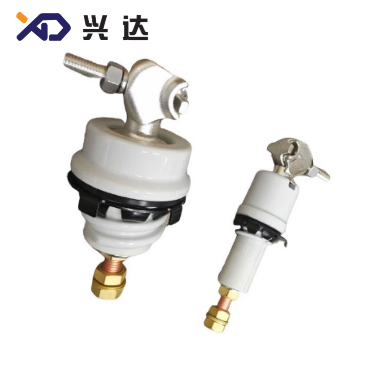
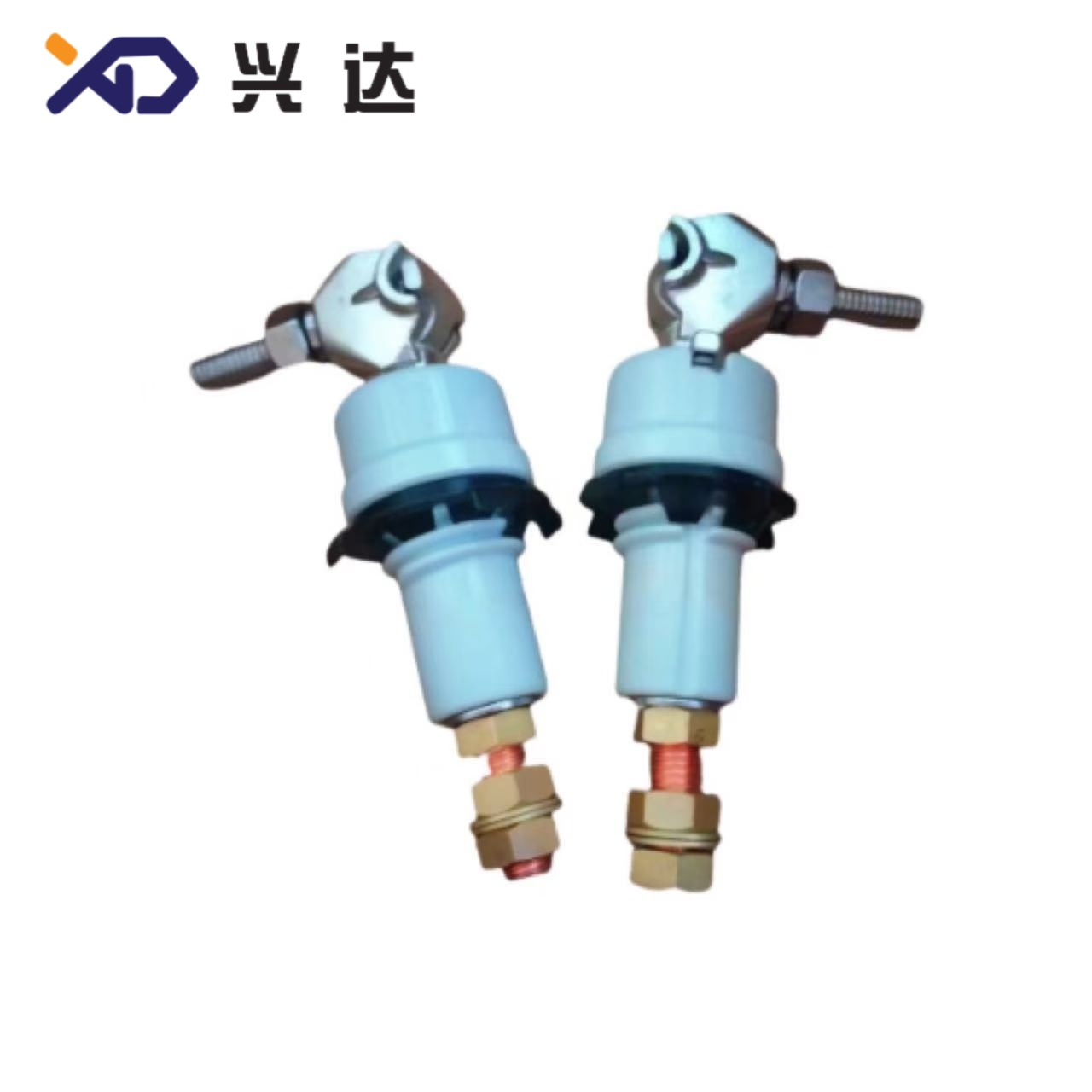
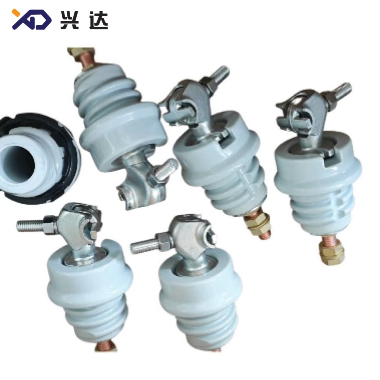
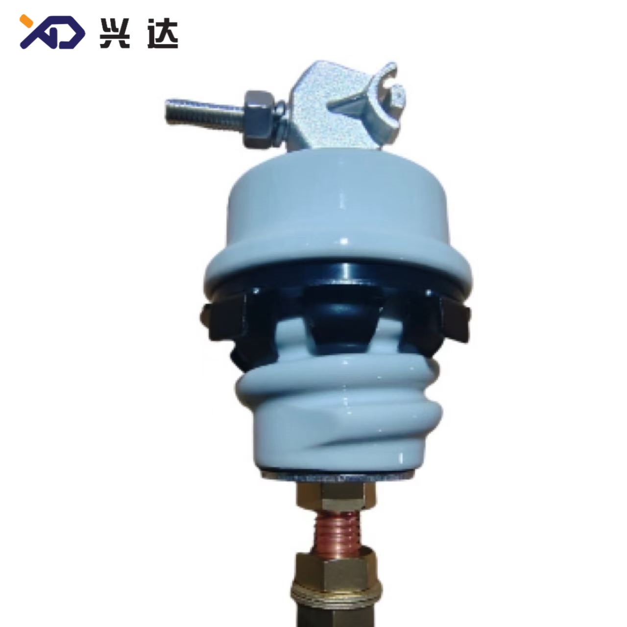
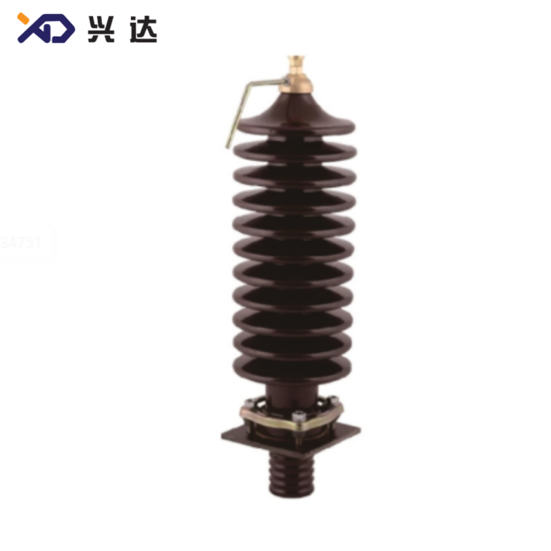
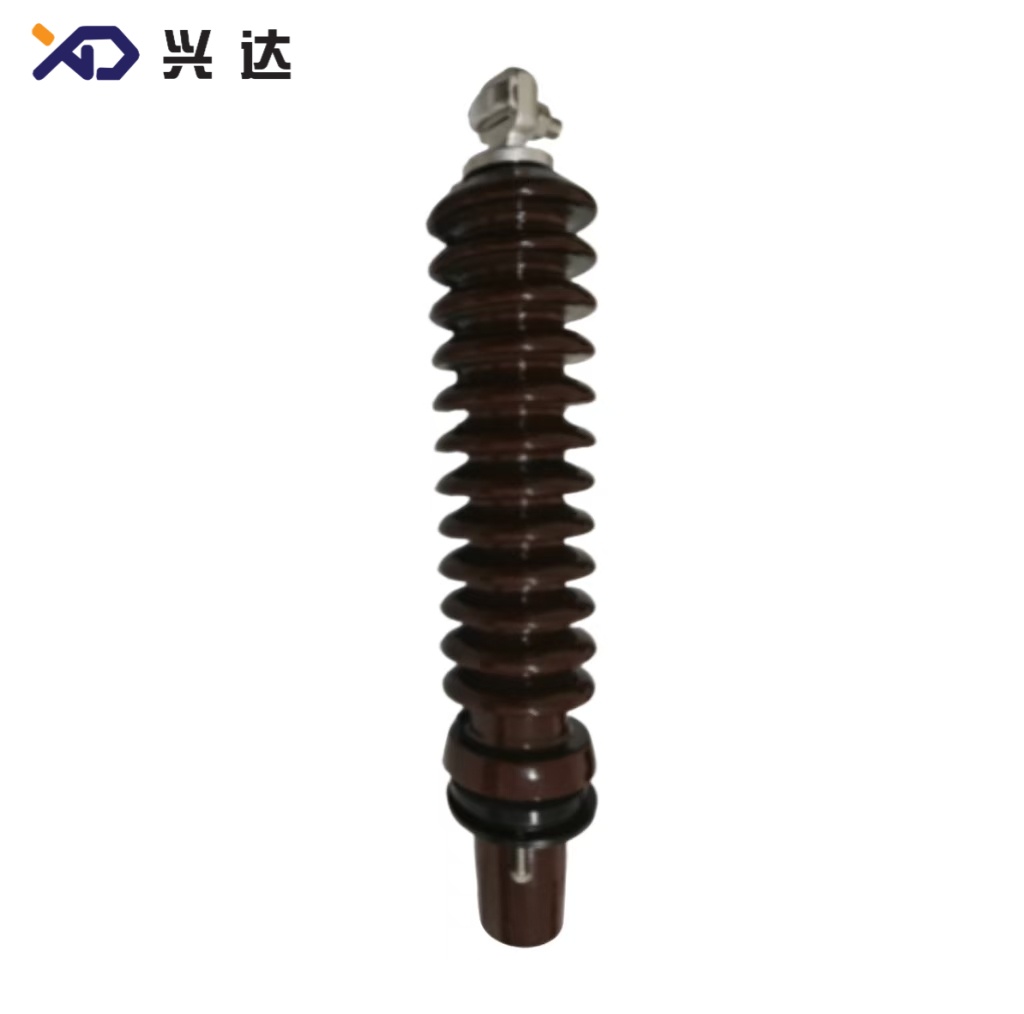
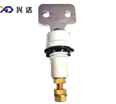
Common connection styles include eyebolt (pin‑type) terminals, single‑hole spade terminals, 2‑hole spade terminals, 4‑hole spade terminals and multi‑hole flange terminals, covering low‑voltage secondary side and medium‑voltage primary‑side transformer applications. The insulator body is most frequently constructed with high‑strength wet‑process porcelain (glazed grey‑white), while polymer composite versions are available for anti‑pollution coastal environmentsAlibaba.co....
Core Advantages of ANSI‑Standard Transformer Bushings
Standardized Interchangeability: Unified tank opening sizes, flange bolt patterns and UNC / UNF imperial threads allow direct drop‑in replacement for ANSI‑designed transformer tanks without custom machining.
Optimized Shed Profile for Outdoor Service: Alternating large‑small porcelain shed design breaks rainwater cascading flow paths, greatly reducing surface flash‑over risk under heavy rain, salt‑fog and industrial pollution conditions.
High Mechanical Robustness: Designed for defined cantilever breaking load, resisting bending stress from heavy overhead cable pulling, vibration and thermal cycling in field installation.
Reliable Oil‑Sealing Performance: Matching ANSI‑standard flower‑basket spin‑grip nut, aluminum clamp and elastomer gaskets ensure long‑term oil‑tight sealing between bushing body and transformer tank wall.
Wide Rating Coverage: Full portfolio ranges from low‑voltage 1.2 kV secondary bushings up to medium‑voltage 34 kV primary bushings, covering continuous current ratings from 55 A up to 3150 A.
Clear Performance Benchmarks: Mandatory test requirements for power‑frequency withstand, impulse BIL level, short‑circuit current resistance and minimum creepage distance are defined in ANSI‑IEEE documents for quality verification.
Main Classification of ANSI Transformer Bushings
ANSI transformer bushings are normally grouped according to rated system voltage class, further subdivided by rated continuous current and terminal connection form (eyebolt / multi‑hole spade flange). Major series are listed below:
| Voltage Class | Typical Current Range | Common Terminal Types | Main Application Position |
|---|---|---|---|
| 1.2 kV Low‑Voltage | 125 A ~ 3150 A | Pin‑type eyebolt, single‑hole, 2‑hole, 4‑hole, 6‑hole spade flange | Transformer secondary low‑voltage side |
| 5 kV Medium‑Voltage | 630 A ~ 4000 A | 4‑hole spade flange | Distribution transformer secondary / intermediate voltage |
| 10 kV Medium‑Voltage | 800 A ~ 2000 A | 4‑hole spade flange | North‑American distribution transformers |
| 15 kV‑18 kV‑25 kV‑34 kV | 55 A ~ 600 A | Eyebolt pin, 2‑hole / 4‑hole spade flange | Transformer primary high‑voltage side |
Note: 1.2 kV series are secondary low‑voltage bushings for transformer output terminals; 15 kV ~34 kV series are primary‑side high‑voltage bushings for incoming overhead line connections.
General Technical & Dimensional Reference Table (Extracted from ANSI‑format transformer bushing dimensional documentation)
Field explanation:
Model: ANSI‑[Voltage]‑[Current]‑[Terminal‑type]
H: Overall total height; h1: height above tank surface; h2: height below tank surface inside oil
Md: Thread size of lower internal conductor stud
Tank opening: Diameter dimension of cut‑out hole on transformer metal tank
Creep distance: External insulation creepage distance along porcelain surface (mm)
1.2 kV ANSI Low‑Voltage Transformer Bushings (125A‑250A / 417A‑1200A / 1400A‑3150A)
| Model | Terminal Style | Tank Opening Diameter | Main Thread Md | Typical Creep Distance |
|---|---|---|---|---|
| ANSI‑1.2KV‑125A‑pin | Eyebolt pin | ∅36.5 mm | Metric / UNC stud | 25 mm |
| ANSI‑1.2KV‑250A‑2‑hole | 2‑hole spade flange | ∅36.5 mm | 5/8"‑11 UNC | 29‑39 mm |
| ANSI‑1.2KV‑417A‑4‑hole | 4‑hole spade flange | ∅71 mm | 3/4"‑10 UNC | 30 mm |
| ANSI‑1.2KV‑1200A‑flange | Multi‑hole heavy‑duty spade | ∅101.6 mm | M38*2.0 / UNC | 50 mm |
| ANSI‑1.2KV‑2000A‑6‑hole | 6‑hole heavy‑duty spade | ∅101.6 mm | M42*2.0 | 50 mm |
5 kV ~10 kV Medium‑Voltage ANSI Bushings
| Model | Terminal Style | Tank Opening Diameter | Creep Distance Reference |
|---|---|---|---|
| ANSI‑5KV‑630A‑4‑hole | 4‑hole spade flange | ∅101.6 mm | 250 mm |
| ANSI‑5KV‑1200A‑4‑hole | 4‑hole heavy‑duty spade | ∅101.6 mm | 250 mm |
| ANSI‑10KV‑800A‑4‑hole | 4‑hole spade flange | ∅101.6 mm | 270‑310 mm |
| ANSI‑10KV‑1200A‑4‑hole | 4‑hole heavy‑duty spade | ∅101.6 mm | 310 mm |
15 kV‑34 kV Primary‑Side ANSI Transformer Bushings
| Model | Terminal Type | Shed Quantity | Tank Opening | Creep Distance (mm) |
|---|---|---|---|---|
| ANSI‑15KV‑55A‑double‑hole | Eyebolt / 2‑hole spade | 6‑8‑10‑single‑shed | ∅71 mm | 279.4‑330 |
| ANSI‑18KV‑55A‑2‑hole | Eyebolt / 2‑hole spade | 8‑10‑single‑shed | ∅71 mm | 380‑450 |
| ANSI‑25KV‑125A‑2‑hole | 2‑hole spade flange | 7‑single‑shed | ∅71.2 mm | 406.4‑523 |
| ANSI‑25KV‑417A‑2‑hole | 2‑hole spade flange | 10‑single‑shed | ∅71.2 mm | 523 |
| ANSI‑34KV‑55A‑2‑hole | Eyebolt pin | 11‑15‑single‑shed | ∅92 mm | 774.7 |
| ANSI‑34KV‑125A‑4‑hole | 4‑hole spade flange | 11‑single‑shed | ∅140 mm | 774.7 |
Important dimensional notes from ANSI drawing documents:
Low‑voltage 1.2 kV small‑current series uses “American flower‑basket spin‑grip nut” for tank mounting, tank opening circle R3, diameter ∅36.5 mm.
Larger‑current 1.2 kV bushing tank opening dimension ∅71 mm with R5 corner radius.
5 kV /10 kV bushing tank opening layout: 4‑M12*70 bolt mounting circle diameter 106.066 mm, inner hole ∅101.6 mm.
15‑34 kV high‑voltage series tank opening varies: ∅71 mm for small‑current eyebolt types; ∅140 mm for heavy‑current multi‑spade flange configurations.
Key Selection Parameters for ANSI Transformer Bushings
When specifying or replacing ANSI transformer bushings, electrical engineers must confirm the following critical parameters to avoid field mismatch:
Rated System Voltage: Confirm transformer primary / secondary nominal system voltage (1.2 kV, 5 kV, 10 kV,15 kV,18 kV,25 kV,34 kV). BIL (Basic Impulse Insulation Level) must match transformer equipment requirements.
Rated Continuous Current: Match maximum transformer winding output or incoming current; oversizing is recommended for overload‑prone distribution transformers.
Terminal Connection Form: Eyebolt pin‑type, single‑hole, 2‑hole, 4‑hole or 6‑hole spade flange; confirm bolt hole quantity, hole diameter and flange width dimension “B”.
Tank Opening Dimension: Verify inner cut‑out hole diameter, mounting bolt circle diameter, number & size of mounting holes on transformer tank. Wrong tank opening dimension will make installation impossible.
Creepage Distance: Select adequate creepage distance according to site pollution grade. Coastal salt‑fog or heavy‑industrial pollution zones require extended creepage length per ANSI C29 standards.
Mechanical Cantilever Load: Check allowable cantilever breaking load for overhead cable pulling stress, especially for pole‑mounted transformers exposed to wind load.
Thread specification: Confirm whether lower conductor stud is UNC / UNF imperial thread or metric thread (Md dimension on drawing).
Overall installation height (H, h1, h2): h1 is height exposed above tank cover; h2 is immersion depth inside transformer oil. Improper h2 may lead to insufficient internal insulation.
Installation & Application Best‑Practices
Sealing assembly: Use matching ANSI‑standard flower‑basket nut or aluminum pressure clamp plus high‑temperature oil‑resistant gaskets. Uneven tightening torque will cause transformer oil leakage.
Orientation check: For high‑voltage shed‑type bushings, ensure sheds face outward to open‑air environment.
Torque control: Follow ANSI recommended torque value for spin‑grip nuts and flange bolts; over‑torque may crack porcelain insulator.
Pollution‑area consideration: In coastal salt‑spray or heavy‑dust industrial sites, select increased creepage distance versions or composite polymer‑insulator ANSI bushings.
Retrofit warning: Do not attempt to fit DIN / IEC‑standard bushings onto ANSI‑designed transformer tanks. Differences in tank opening, flange pattern and thread standards cannot be compensated only by gaskets or adapters and will create safety hazards.
Common Failure Modes of ANSI‑Type Transformer Bushings
Oil leakage at tank interface: Caused by gasket aging, uneven bolt torque, mis‑matched flower‑basket nut / aluminum clamp hardware.
External surface flash‑over: Occurs when creepage distance is insufficient for pollution environment or insulator surface accumulates heavy dirt, salt deposit.
Porcelain cracking: Result of excessive cantilever bending load, over‑tight mounting torque or mechanical impact during transportation / installation.
Internal over‑heating: Poor contact resistance at spade‑flange or eyebolt terminal connections under high continuous current.
Regular preventive maintenance includes visual inspection for oil seepage, porcelain crack and surface contamination cleaning.
Standards Reference List for ANSI Transformer Bushings
IEEE C57.19.00: General requirements and test procedures for outdoor power apparatus bushings
IEEE C57.19.01: Performance requirements for power‑transformer bushings
ANSI C29.9: Wet‑process porcelain insulators for power apparatus
ANSI C84.1: Voltage ratings for electric power systems and equipment
Categories
Contact Us
Contact: Tianjin Delda Trading Co., Ltd
WhatsApp: +86 13662056855
Tel:
E-mail: solomon20210701@tjxddq.com
Add: Unit‑101, Workshop 3, Bozhong Automobile Industrial Park, No.5 Xianghui Road, Intersection of Xianghui Road and Gaoying Road, Beizhakou Town, Jinnan District, Tianjin, China